Understanding Cisco ACI Access Policies: A Practical Guide

Understanding Cisco ACI Access Policies doesn’t have to be complicated. This practical guide simplifies the core concepts and clearly shows you what you need to know.
Secure and controlled access is fundamental to any network. This guide walks you through both the essentials and more advanced topics of Cisco ACI Access Policies, demonstrating how to apply them effectively in your environment and designs.
1. The End-to-End Workflow for Cisco ACI Access Policy Deployment.
1.1. Interface Policies Configuration Workflow.
1.2. Leaf Switches Policies Configuration Workflow.
2. Leaf Access Port configuration.
3. Leaf Port Channel (PC) configuration.
4. Leaf Virtual Port Channel (vPC) configuration.
1. The End-to-End Workflow for Cisco ACI Access Policy Deployment.
Cisco Application Centric Infrastructure (ACI) redefines network management with its policy-driven automation, moving away from traditional device-by-device configurations. At the heart of this transformative approach lies Access Policies, which dictate how physical network devices connect to the ACI fabric and how virtual and physical workloads access network services.
1.1. Interface Policies Configuration Workflow.
-
VLAN Pools A VLAN Pool defines a range (or multiple ranges) of VLAN IDs that are permitted for use on leaf switch ports for EPG encapsulation. It doesn’t provision the VLANs themselves but rather reserves them for use.
- Domains and Domain Types Purpose: Domains act as a bridge, linking VLAN Pools with policies and the infrastructure. They define the scope where a particular VLAN pool can be utilized and by what type of entity.
-
Physical Domains integrate bare-metal servers, physical appliances (e.g., firewalls, load balancers, non-virtualized servers), or other physical devices directly connected to ACI leaf ports.
-
Fibre Channel Domains are primarily used for integrating Fibre Channel over Ethernet (FCoE) storage networks with the ACI fabric. This allows the ACI fabric to act as a converged network that carries both IP and FCoE traffic.
-
External L3 Domains connect the ACI fabric to external Layer 3 (routed) networks or traditional routers outside the ACI fabric (Used by L3OUT).
-
External Bridge Domains connect the ACI fabric to external Layer 2 (bridged) networks or switches outside the ACI fabric. This is used when you need to extend Layer 2 segments from the ACI fabric to external devices without routing (Used by L2OUT).
-
- Attachable Access Entity Profile (AAEP) The AAEP effectively defines which VLANs are allowed on an interface or group of interfaces. It does this by referencing Domains, which in turn reference VLAN Pools. If we compare with old fashion switch configuration it should be
switchport trunk allowed vlanCommon Scenarios for AAEP Scope/Design:
-
One-to-one with Domains: Often, you’ll create an AAEP for each type of domain (Physical AAEP, 1.VMM AAEP, L3Out AAEP, L2Out AAEP, FCoE AAEP) to clearly separate their respective VLAN pools and interface associations.
-
Functional Grouping: You might create AAEPs based on functional groups of ports, e.g., “ServerFarm_AAEP” that encompasses all necessary domains (physical and VMM) and VLANs for server connectivity.
-
- Interface Policy Group (IPG) acts as a collection point for individual “interface policies.” These individual policies define specific Layer 1 or Layer 2 parameters for a port.
Key Interface Policy Group Policies are:
- Link Level Policy (speed, duplex, auto-negotiation).
- CDP (Cisco Discovery Protocol) Policy (enable/disable).
- LLDP (Link Layer Discovery Protocol) Policy (enable/disable).
- LACP Policy (for Port Channels: active, passive, on, port priority).
- Storm Control Policy control Broadcast, Unknown Unicast, and Multicast (BUM).
- MCP (Mis-Cabling Protocol) Policy.
- Spanning Tree related policies (BPDU Guard/Filter).
-
L2 Interface Polices (VLAN scope Global or Port Local).
- Interface Profile

Figure 1. Representing Interface Policies Configuration Flow.
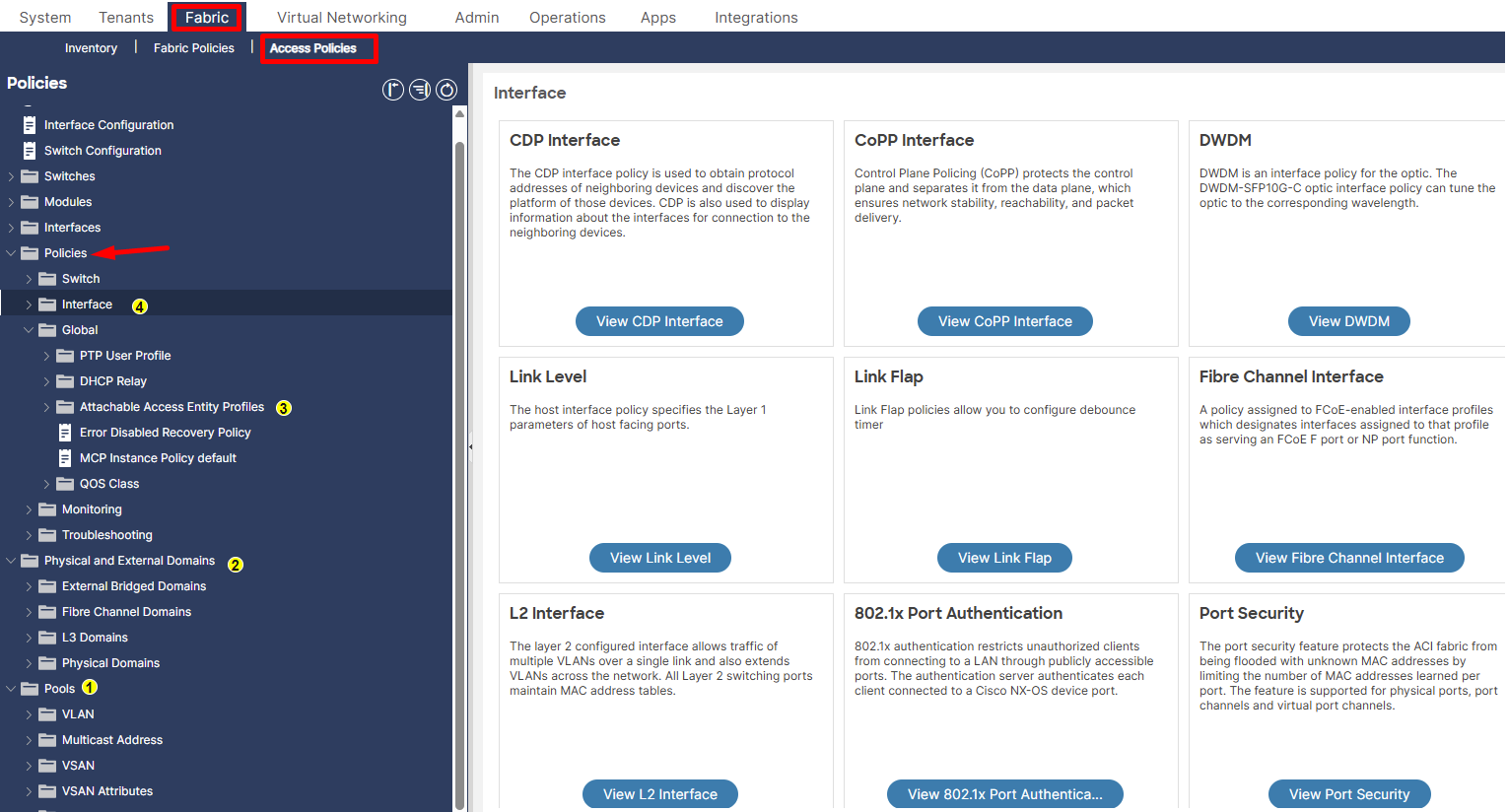
Figure 2. Interface Policy Configuration within the Cisco APIC UI.

Figure 2.1. Interface Policy Configuration within the Cisco APIC UI.
1.2. Leaf Switches Policies Configuration Workflow.
- Leaf Switches Policy Groups they control the behavior of the entire leaf switch. This allows for consistent application of switch-level configurations to multiple leaf nodes selected by a Leaf Switch Profile.
Key Leaf Switches Policy Groups are:
- Spanning Tree
- Monitoring polices
- CoPP Leaf Policy
- NetFlow Node Policy
- BFD IPv4 and IPv6 Policy

Figure 3. Representing Leaf Switch Policies Configuration Flow.
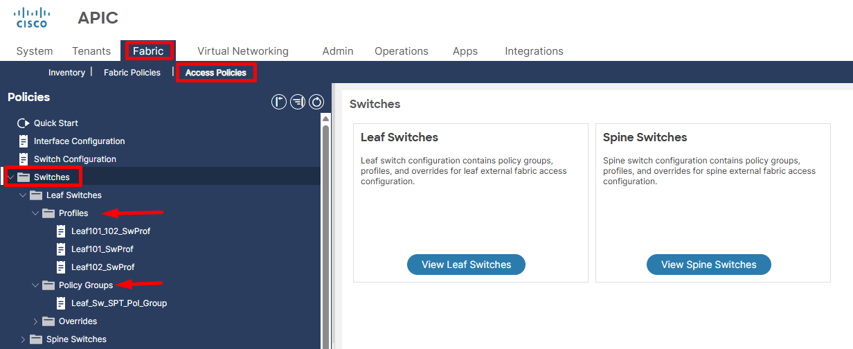
Figure 4. Leaf Switch Policies Configuration within the Cisco APIC UI.

Figure 5. Full configuration flow for interface and leaf switch polices.
2. Leaf Access Port configuration.
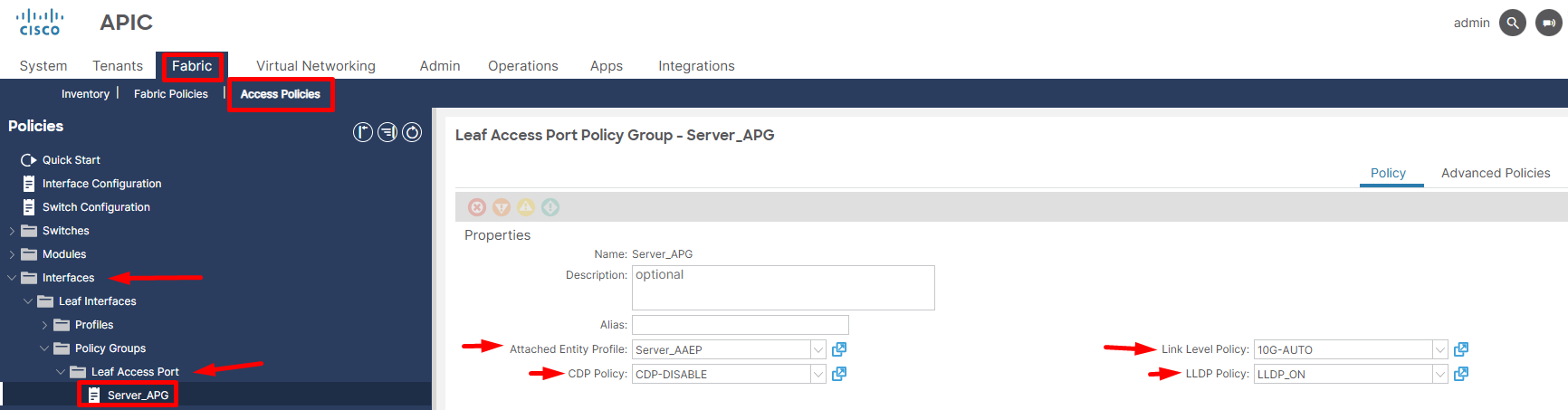
Figure 6. Implementation of an Interface Policy Group within the Cisco APIC user interface (UI).
After creating the Leaf Interface profile and attaching it to the Leaf Switch profile, we add specific ports under the Leaf Interface profile and select the appropriate Interface Policy Group. This approach provides reusability and simplifies automation. For Particular case we created Leaf Access Port Policy Group like below and attached to port eth1/1 inside specific Leaf Interface Profile.
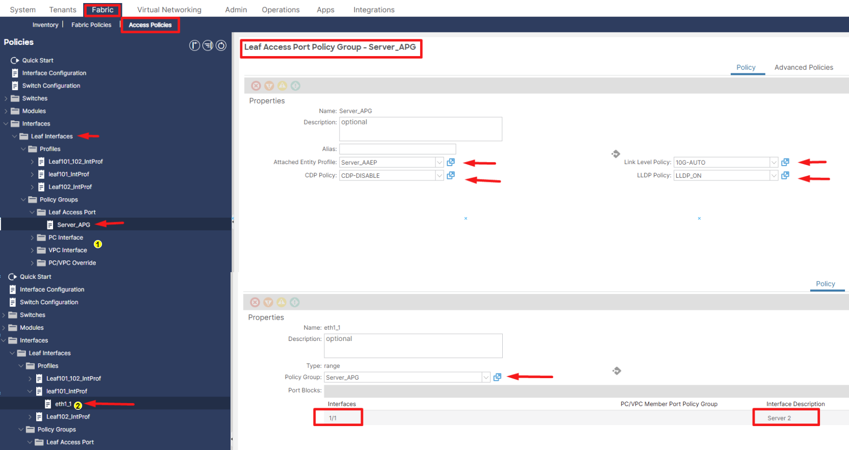
Figure 7. Representing creation of Access port policy group and attaching to specific Leaf Interface profile.

Figure 8. End to end workflow to setup access port up and running on leaf switch.
3. Leaf Port Channel (PC) configuration.
The foundational workflow for configuring a Port Channel in Cisco ACI closely mirrors that of a standard Access Port; however, a key distinction lies in the explicit inclusion and application of an LACP Policy within the associated Interface Policy Group, which is then specifically leveraged for the two designated physical ports on a single leaf switch to form the logical Port Channel.
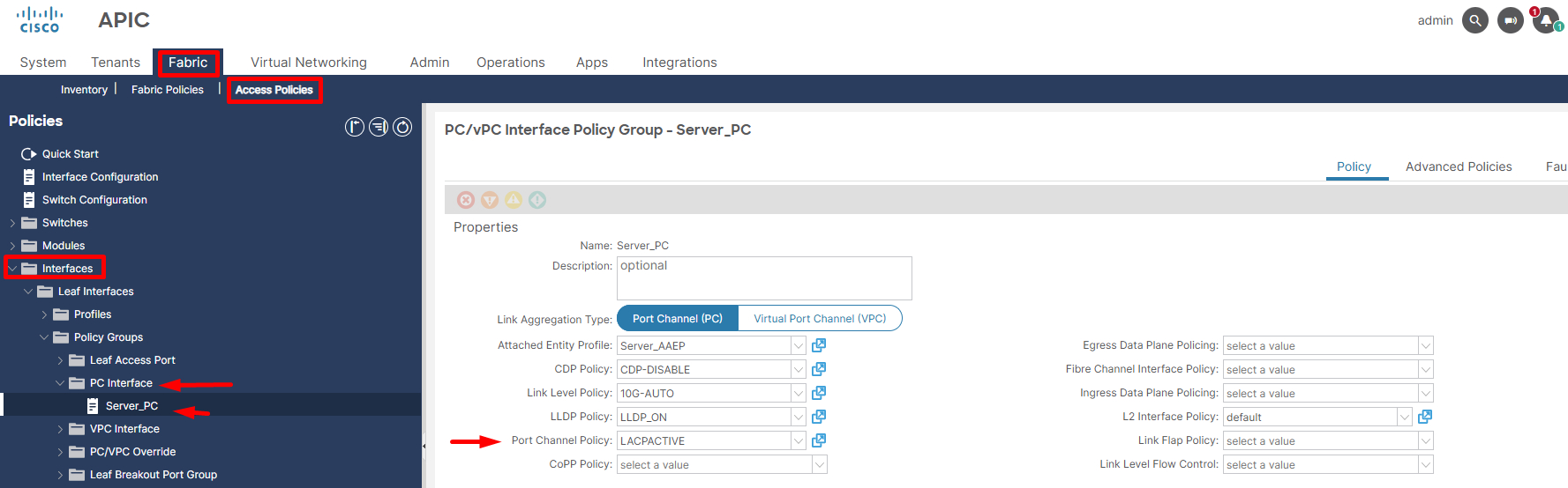
Figure 9. Representing creation of Port Channel policy group.

Figure 10. End to end workflow to setup Port Channel (PC) up and running on leaf switch.
4. Leaf Virtual Port Channel (vPC) configuration.
Virtual Port Channel (vPC) significantly enhances network resilience and operational uptime by logically combining two physical ports, each residing on a separate Cisco Nexus leaf switch, into a single, aggregated link. This innovative design provides superior high availability, as it creates active-active forwarding paths, ensuring that traffic can seamlessly continue to flow even if one of the leaf switches or an individual link experiences a failure.
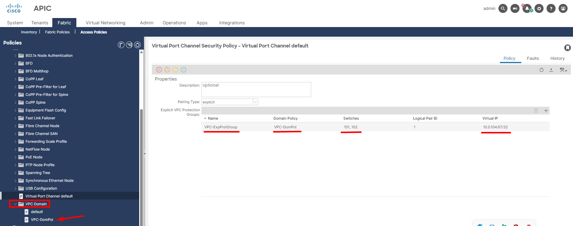
Figure 11. Representing creation of Virtual Port Channel (vPC) policy group.

Figure 12.End to end workflow to setup Virtual Port Channel (vPC) up and running on leaf switches.