Cisco ACI's Core Building Blocks: Tenants to EPGs Explained

In the world of modern data centers, Cisco Application Centric Infrastructure (ACI) stands out as a powerful solution for network automation, policy enforcement, and application agility.
This post will demystify the core building blocks of Cisco ACI, guiding you through the concepts of Tenants, VRFs (Virtual Routing and Forwarding), Bridge Domains, Application Profiles, and Endpoint Groups (EPGs). By the end of this explanation, you'll have a clear understanding of how these elements work together to form a robust and flexible network fabric, enabling you to design and implement ACI solutions with confidence. Let's dive in!
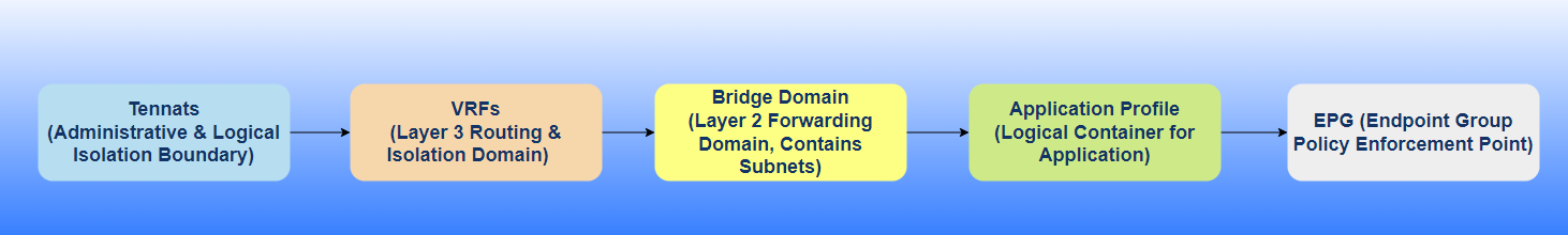
Figure 1. Workflow of Tenant to EPG deployment.
1. Understanding the Tenant: The Administrative Boundary.
2. VRF (Virtual Routing and Forwarding): The Layer 3 Isolation Domain.
3. Bridge Domain (BD): The Layer 2 Forwarding Domain.
3.1. Subnet Configuration within a Bridge Domain: Defining IP Address Space & Reachability.
4. Application Profile (AP): The Application Logical Container.
5. EPG (Endpoint Group): The Granular Policy Enforcement Point.
6. Endpoint Security Groups (ESGs): Decoupling Security from Forwarding
1. Understanding the Tenant: The Administrative Boundary.
In the ACI object model, the Tenant (fvTenant) is the root of a policy tree for a given set of configurations. All subsequent networking objects (VRF, BD, EPG, etc.) are children of a Tenant.
Default Tenants: When you initialize an ACI fabric, three default tenants are automatically created:
common: This tenant is for shared resources that can be accessed by all other tenants. Common uses include shared Layer 3 Out (L3Out) connections to external networks, common services like DNS or DHCP, and shared Layer 4-7 services (e.g., firewalls, load balancers). Objects in the common tenant can be consumed by other tenants via contracts.
infra (Infrastructure): This tenant is used for internal ACI fabric communications. It contains policies related to fabric discovery, image management, VXLAN overlay, and other underlying infrastructure functions. It’s generally not directly configured by users unless specifically instructed by Cisco for advanced scenarios like Multi-Pod or Multi-Site deployments.
mgmt (Management): This tenant is dedicated to managing the ACI fabric itself. It defines policies for in-band and out-of-band management access to the APIC controllers and fabric switches. No Direct Network Construct: A Tenant itself doesn’t map directly to a traditional network construct like a VLAN, VRF, or physical interface.
Globally Unique Names: Tenant names must be globally unique across the ACI fabric.
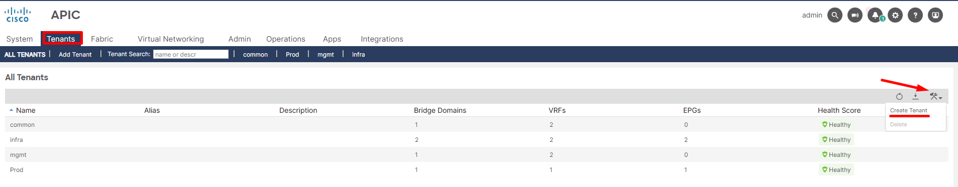
Figure 2. Tenant deployment workflow.
2. VRF (Virtual Routing and Forwarding): The Layer 3 Isolation Domain.
Layer 3 Isolation: The fundamental purpose of a VRF in ACI, just like in traditional networking, is to provide Layer 3 isolation. Each VRF has its own independent routing table, IP address space, and set of routing protocols. This means that traffic within one VRF cannot directly communicate with traffic in another VRF unless explicitly configured to do so (e.g., via a firewall or inter-VRF routing policies).
Routing Instance: A VRF is essentially a virtual routing instance. It holds the routing information (routes, ARP/ND entries) for the subnets and endpoints associated with it.
Tenant Scoped: A VRF is always contained within a Tenant. It’s a child object of a Tenant (fvCtx in the ACI object model). This means that a VRF belongs to a specific administrative domain and its policies are managed under that tenant.
Policy Control Enforcement Preference:
- “Enforced” (Default and Recommended): This means that all communication between EPGs within this VRF (or between an EPG in this VRF and an external network) requires a Contract.
- “Unenforced”: This setting implies that all EPGs within this VRF can communicate freely with each other by default, without the need for explicit Contracts. While it simplifies initial setup, it bypasses ACI’s micro-segmentation capabilities and is generally discouraged for production environments where granular security is a requirement.
Preferred Group: setting, enabled at the VRF level, allows all EPGs within that VRF to communicate with each other by default if they are part of the preferred group.
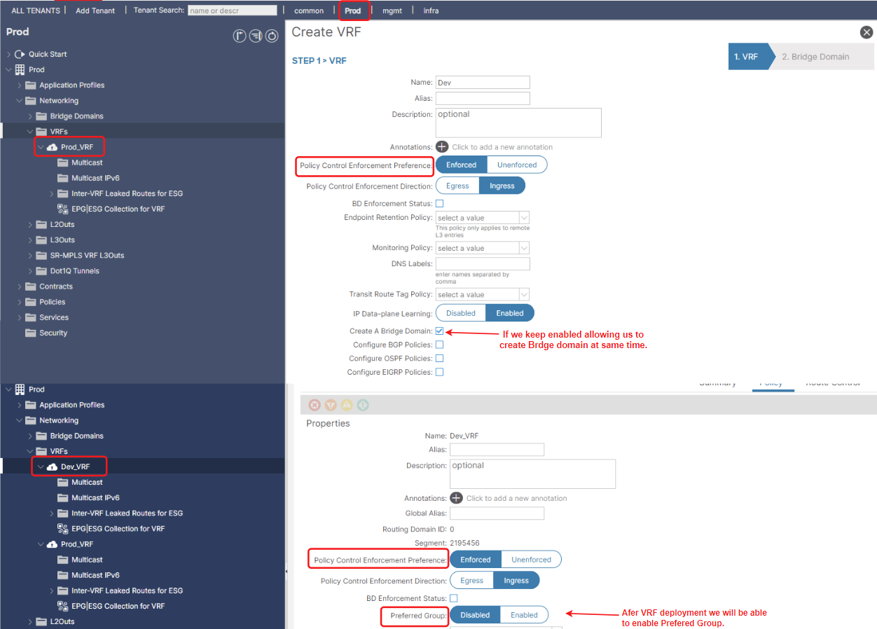
Figure 3. VRF deployment workflow
3. Bridge Domain (BD): The Layer 2 Forwarding Domain.
In Cisco ACI, a Bridge Domain (BD) is a critical logical construct that represents a Layer 2 forwarding domain. It’s the ACI equivalent of a traditional VLAN or broadcast domain, but with significantly enhanced capabilities and policy integration.
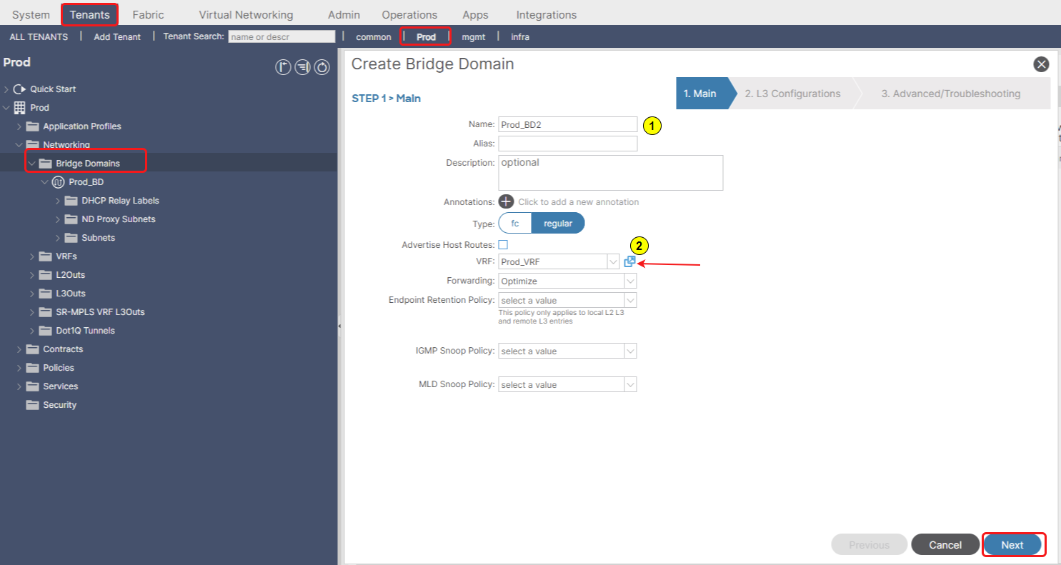
Figure 4. First step in Bridge Domain deployment.
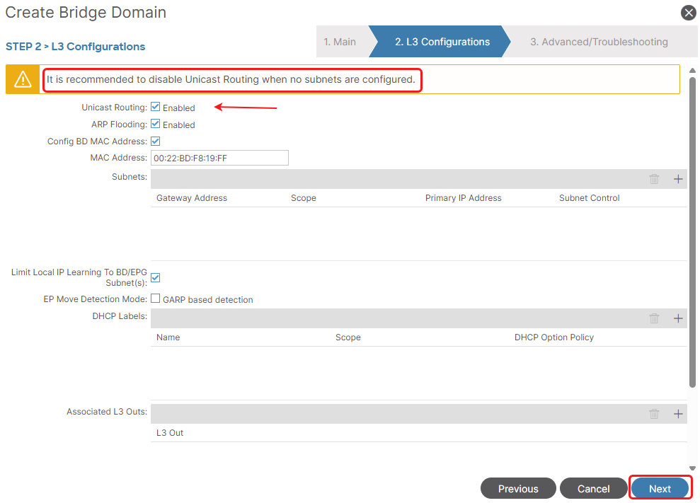
Figure 5. Second step in Bridge Domain deployment.
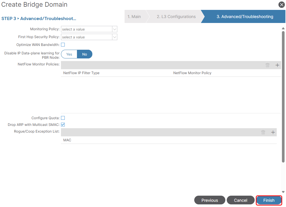
Figure 6. Third step in Bridge Domain deployment.
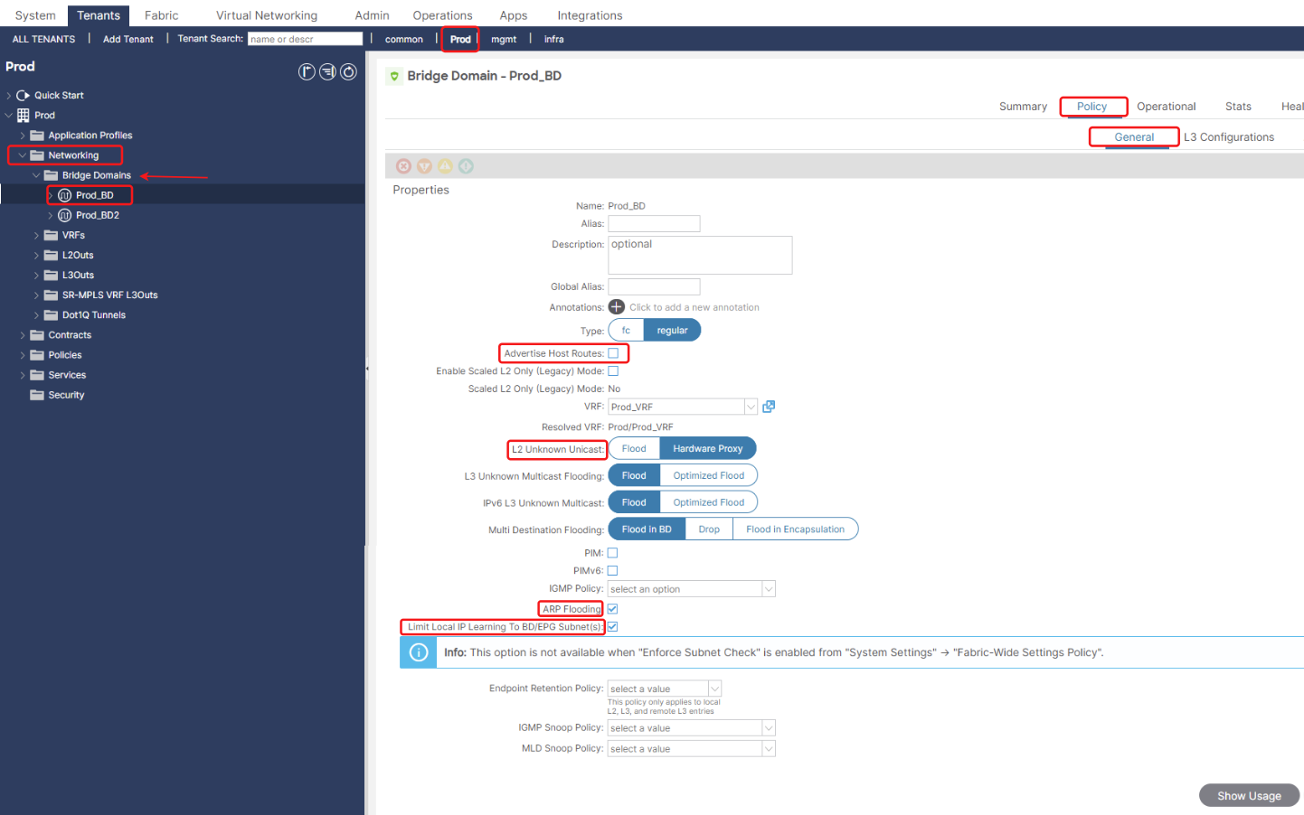
Figure 7. Bridge Domain L2 features.
Advertise Host Routes: By advertising a precise /32 (or /128) route for each individual endpoint, external routers learn the exact leaf switch (and pod/site) where the endpoint resides. This directs traffic directly to the optimal entry point into the ACI fabric.
L2 Unknown Unicast Handling: This setting defines how the ACI fabric handles unknown unicast traffic within the Bridge Domain:
-
Hardware Proxy (Default and Recommended): This is the most efficient and scalable method. When a leaf switch receives an unknown unicast frame, it doesn’t flood it everywhere. Instead, it sends the frame to a spine proxy. The spine acts as a central lookup point, and if it knows the destination MAC, it forwards the frame directly to the correct leaf. If the MAC is unknown to the spine, only then does the spine flood it to relevant leaves. This significantly reduces flood domains.
-
Flood: This behaves like traditional Ethernet. Unknown unicast frames are flooded to all leaf switches that have an endpoint associated with this Bridge Domain. This can be inefficient and generate unnecessary traffic, especially in large environments.
Optimize ARP Flooding: This option, when enabled, means that the ACI fabric will proxy ARP requests for known MAC addresses instead of flooding them. This reduces broadcast traffic.
Limit local IP learning to BD/EPG subnets: Restrict IP Learning: The ACI leaf switches connected to this Bridge Domain will only learn IP addresses for endpoints that fall within the explicitly defined IP subnets configured under that particular Bridge Domain, or the subnets defined within the EPGs that reside within that BD. It will ignore Out-of-Subnet IPs.
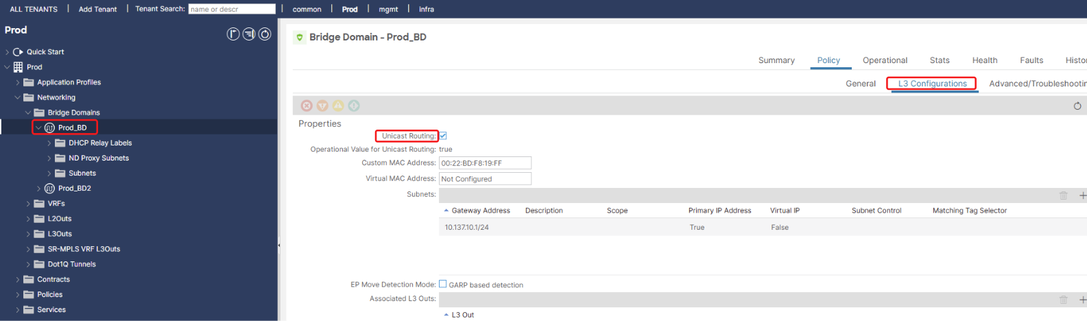
Figure 8. Bridge Domain L3 features.
IP Unicast Routing (Enabled/Disabled):
- If enabled, the ACI fabric will provide a distributed default gateway (Anycast Gateway) for any IP subnets defined within this Bridge Domain. This means the Layer 3 routing for endpoints in this BD is handled directly by the ACI leaf switches. This is the typical configuration for routed networks.
- If disabled, the ACI fabric will not provide a default gateway for the subnets in this BD. This is often used for: Networks where an external router or firewall provides the default gateway. In such cases, the ACI fabric simply acts as a transparent Layer 2 forwarding plane.
3.1 Subnet Configuration within a Bridge Domain: Defining IP Address Space & Reachability.
Each Bridge Domain can have one or more IP subnets associated with it. These subnets represent the IP address space for the endpoints connected to the Bridge Domain. Additionally, subnets can also be created directly under an EPG, but their purpose in that context is different: it facilitates Route Leaking and Shared Services between VRFs/Tenants with policy granularity.
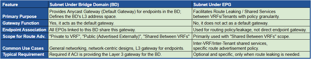
Table 1. Comparing Subnets: Bridge Domain vs. EPG.
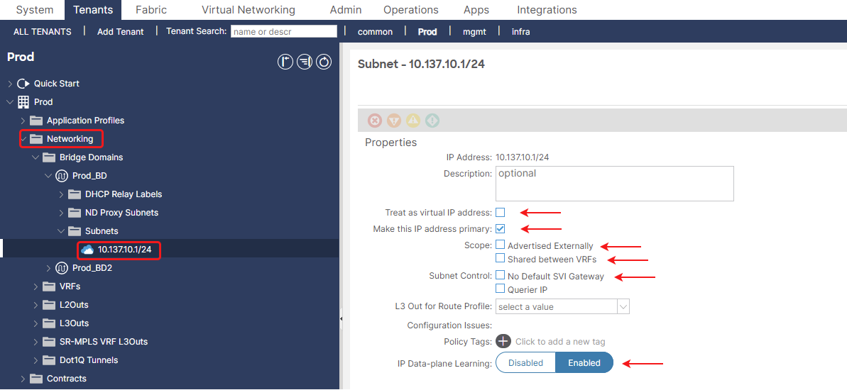
Figure 9. Subnet deployment within specific Bridge Domain.
Treat as Virtual IP address: Special handling for HA (Active/Standby) external device VIPs, ensuring proper learning and failover during HA events.
Make this IP address primary Designates a preferred source IP for the BD’s own control plane traffic when multiple subnets exist within this BD.
Advertised Externally: Advertises individual /32 (or /128) host routes for learned endpoints to external networks via L3Outs, optimizing traffic paths and VM mobility.
Shared Between VRFs: This option allows the subnet to be “leaked” and reachable by other VRFs within the same or different Tenants, usually in conjunction with Contracts for inter-VRF communication.
No Default SVI Gateway: Disables ACI’s pervasive gateway for this specific subnet (useful for secondary IPs or external gateways).
IP Data Plane Learning Enables dynamic learning of endpoint IP addresses by observing network traffic (typically enabled for general endpoints).
4. Application Profile (AP): The Application Logical Container.
In Cisco ACI, an Application Profile (AP) is a logical container that groups together all the Endpoint Groups (EPGs) and Contracts needed to deploy a specific application or service. It provides a higher-level abstraction for managing application-centric policies within the ACI fabric. The primary purpose of an Application Profile is to shift the focus from network-centric configuration to application-centric configuration. Instead of configuring network policies based on VLANs or subnets, you define policies based on the application components and their communication requirements.
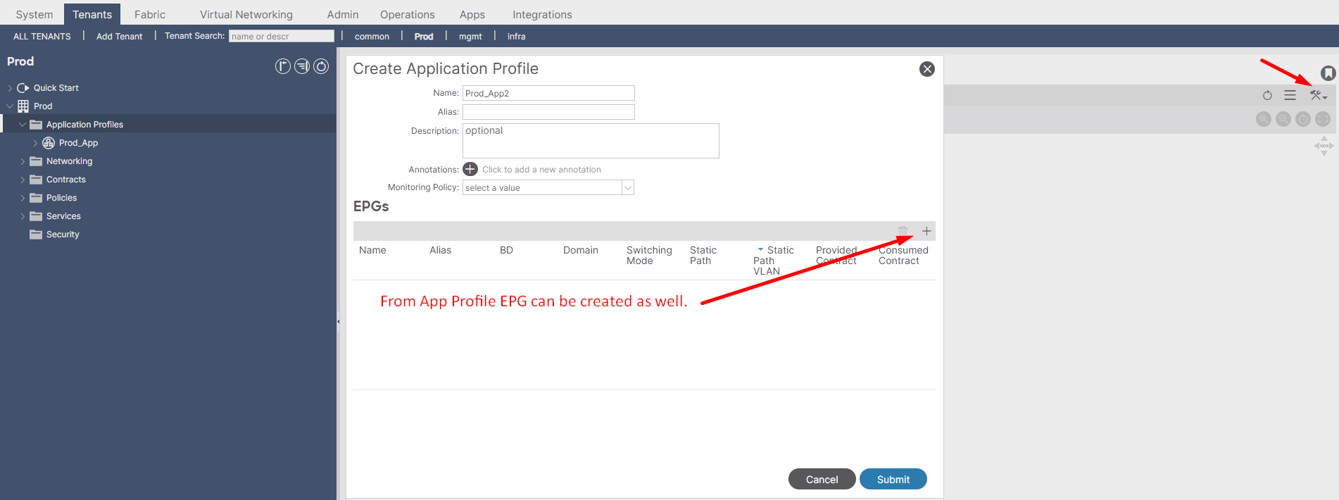
Figure 10. Deployment of Application profile.
5. EPG (Endpoint Group): The Granular Policy Enforcement Point.
An EPG is the smallest and most critical unit to which policy (Contracts) is applied. If two endpoints are in the same EPG, they can communicate by default (unless otherwise restricted by other policies like Preferred Group or micro-segmentation). If they are in different EPGs, communication between them is blocked by default, and a Contract is required to permit specific traffic flows. This is ACI’s core “whitelist” security model. EPGs support micro-segmentation through features like intra-EPG isolation, which prevents communication between endpoints within the same EPG if required.
Type Of EPGs:
- “Classic” EPG which is representing endpoints, they can be physical servers, virtual machines, network-attached storage devices, or even clients on the internet.
- Layer 2 external outside network instance endpoint groups (l2extInstP).
- Layer 3 external outside network instance endpoint groups (l3extInstP).
- Management Endpoints groups (mgmtOoB, mgmtInB) are used for securing access to the ACI fabric’s management plane, either through a dedicated out-of-band management network or via in-band access within the fabric itself.
Figure 11. Deployment of EPG under application profile.
To provision EPG on the port/switch we have to methods:
- Static Ports: Explicitly links an EPG to a specific physical interface.
- Static Leafs (via AAEP): Links an EPG to a logical group of interfaces defined by an AAEP, effectively pushing the EPG’s VLAN to all ports associated with that AAEP.
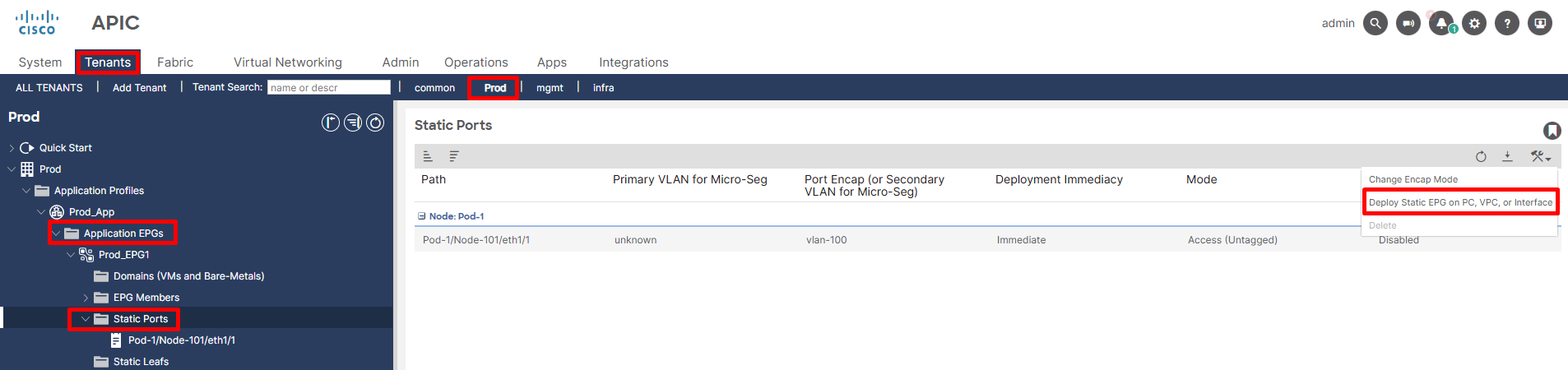
Figure 12. EPG to Leaf Port Static Assignment.
6. Endpoint Security Groups (ESGs): Decoupling Security from Forwarding
Decoupling Security from Forwarding: This is the core architectural shift and primary benefit of ESGs compared to EPGs. EPGs combine both forwarding (VLAN/VXLAN binding, BD association) and security, whereas ESGs aim to provide security policy based on attributes, independent of the underlying network forwarding.
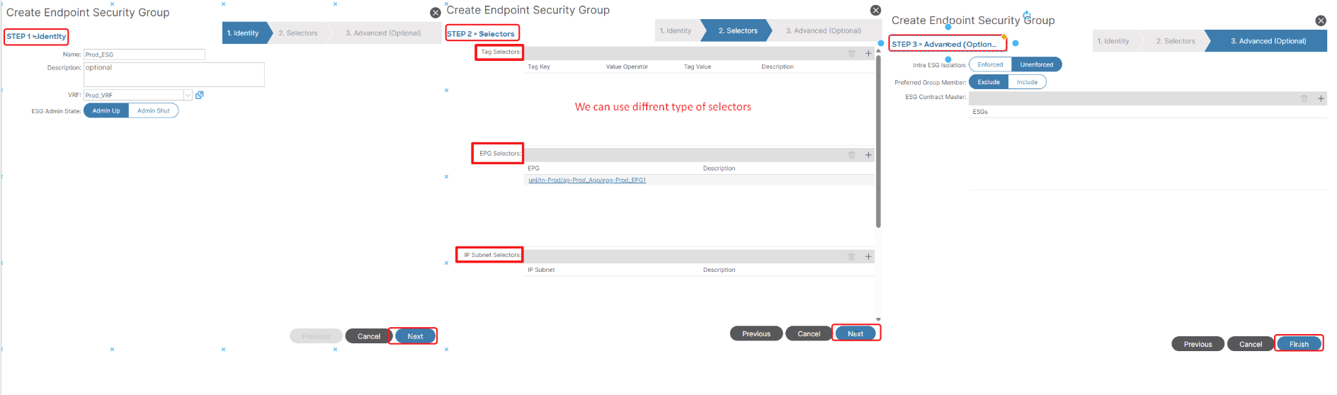
Figure 13. Defining Endpoint Security Groups (ESGs) for Policy Decoupling.
After defining your ESGs, you will create Contracts as usual. Associate the ESG as a Provider or Consumer of the contract, just like you would with EPGs.
Remember: Contracts typically apply ESG-to-ESG, ESG-to-L3Out External EPG, ESG-to-L2Out External EPG or ESG-to-vzAny.
By using ESGs, ACI provides an additional layer of flexibility and powerful tools for defining and enforcing security policies, especially beneficial in complex and evolving data center environments.