Designing with Cisco ACI

Welcome to “Designing with Cisco ACI,” where we will dive into the Cisco ACI principals of creating robust, scalable, and efficient network architectures using Cisco’s Application Centric Infrastructure (ACI).
In today’s rapidly evolving IT landscape, the ability to design flexible and resilient networks is more critical than ever. This blog will provide you with ideas on what you can do with Cisco ACI fabric, covering various use cases and key design points. It will be especially valuable for those preparing to deploy Cisco ACI and who are still unsure which design to choose. The following Cisco ACI design types will be the topics of discussion:
1. Cisco ACI Traditional Single Pod.
2. Cisco ACI Remote leaf.
3. Cisco ACI Mini.
4. Cisco ACI Multi-Pod Interconnect via IPN.
5. Cisco ACI Multi-Pod Interconnect Spine back to back.
6. Cisco ACI Multi-Site.
7. Multi-Pod - Multi-Site hybrid deployment.
So let’s start!
1. Cisco ACI Traditional Single Pod.
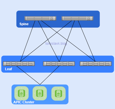
Figure 1. Cisco ACI Single Pod Fabric.
Main Characteristics:
- Architecture: Consists of a single APIC (Application Policy Infrastructure Controller) cluster managing one ACI fabric.
- Management: Centralized management with a single point of control.
- Scalability: Limited to the capacity of one fabric.
- Latency: Lower latency within the single fabric.
- Failure Domain: Single failure domain, meaning any issue can affect the entire fabric.
Key Differences between Cisco ACI Single and Multi Pod Fabric:
- Scalability: Multi-Pod offers greater scalability by allowing multiple Pods to be managed under one APIC cluster.
- Resiliency: Multi-Pod improves resiliency by isolating failure domains.
- Latency: Single Pod has lower latency within the fabric, while Multi-Pod may have slightly higher latency due to inter-Pod communication
2. Cisco ACI Remote leaf.
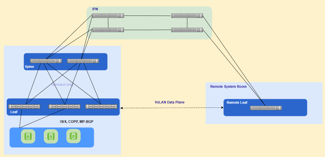
Figure 2. Cisco ACI Extending fabric with remote leaf to remote location.
Main Characteristics:
- VxLAN Tunnels: Unicast traffic is forwarded through VXLAN tunnels over Layer 3. This ensures that traffic between the remote leaf and the main fabric is encapsulated and securely transmitted.
- Head End Replication (HER): For Layer 2 broadcast, unknown unicast, and multicast (BUM) traffic, Head End Replication (HER) tunnels are used. This method avoids the need for multicast in the WAN.
- Policy Consistency: All policies defined in the main data center are consistently applied to the remote leaf switches, ensuring uniform policy enforcement across the entire fabric.
- Local Switching: Traffic between endpoints connected to the remote leaf is switched locally, while traffic requiring spine proxy services is forwarded to the main fabric.
Inter-Pod Network Requirements for Remote Leaf deployment:
- L3 network should support 50 Bytes overhead for VxLAN if we have default MTU 1500 Bytes.
- The latency between the ACI main DC and the remote Leaf should be less than 300 msec Round Trip Time (RTT)
- A minimum of 100 Mbps bandwidth in the IP Network. Starting from Cisco ACI Release 4.2.4, the requirement has been lowered to 10 Mbps of bandwidth.
- The remote leaf solution requires the /32 Tunnel End Point (TEP) IP addresses of the remote leaf switches and main data center leaf/spine switches to be advertised across the main data center and remote leaf switches without summarization.
Use Cases:
Satellite/Co-Location Data Centers:
Enterprises or service providers often have a main data center and several smaller satellite data centers distributed across multiple locations.
Disaster Recovery Sites:
Organizations need to maintain disaster recovery sites to ensure business continuity in case of a failure at the primary site.
Branch Offices:
Companies with multiple branch offices require consistent network policies and centralized management.
Edge Computing:
With the rise of edge computing, data processing is moved closer to the source of data generation example telco 5G.
3. Cisco ACI Mini.
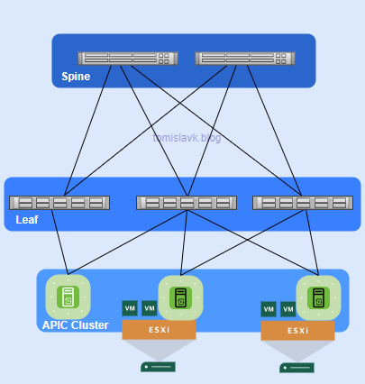
Figure 3. Cisco ACI mini - connecting virtual APICs to fabric.
Main Characteristics
- APIC Cluster: Consists of one physical APIC and two virtual APICs (vAPICs) running in virtual machines. Reduces the physical footprint and cost of the APIC cluster, making it suitable for environments with limited rack space or budget.
- Deployment Scenarios: Ideal for colocation facilities, single-room data centers, or any scenario where full-scale ACI installations are impractical.
- Management and Policy: Provides centralized management and policy enforcement similar to full-scale ACI deployments. Does not support features like Multi-Pod, Virtual Pod, or Remote Leaf switches.
- Integration: Multi-Site Support: Can be integrated with Cisco ACI Multi-Site for broader deployment scenarios.
- Time Synchronization: Requires the physical APIC and the ESXi server hosting the virtual APICs to be time-synced with the same NTP server to avoid synchronization issues.
Use Cases:
- Colocation Facilities: Businesses that use colocation facilities to host their IT infrastructure.
- Single-Room Data Centers: Small businesses or branch offices with a single-room data center.
- Development and Test Environments: Organizations that need a dedicated environment for development and testing.
- Edge Computing: Deployments at the edge of the network, closer to data sources.
4. Cisco ACI Multi-Pod Interconnect via IPN.
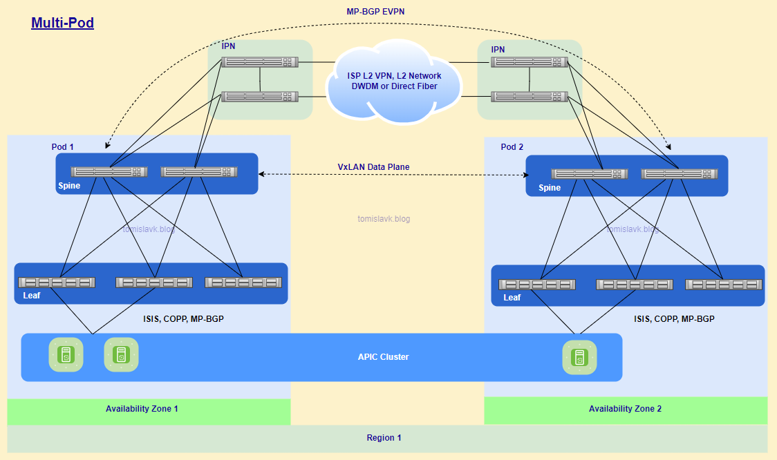
Figure 4. Cisco ACI Multi-Pod Interconnected via Inter-Pod Network.
Main Characteristics
- Centralized Management: Managed by a single APIC cluster, providing a unified management and policy domain across all Pods1.
- Fault Isolation: Control plane protocols (e.g., IS-IS, COOP, MP-BGP) operate independently within each Pod, enhancing fault isolation.
- Scalability: Supports the interconnection of multiple Pods, allowing for greater scalability and flexibility in data center design.
- Inter-Pod Network (IPN): Pods are connected via a Layer 3 Inter-Pod Network (IPN), which uses VXLAN encapsulation for data plane traffic and MP-BGP EVPN for control plane communication.
- End-to-End Policy Enforcement: Ensures consistent policy enforcement across all Pods, maintaining uniform security and network policies.
- Resiliency: Isolated failure domains within each Pod reduce the impact of failures, enhancing overall resiliency.
- Geographical Flexibility: Pods can be located in different physical data centers, including geographically dispersed locations, with up to 50 ms RTT latency.
Inter-Pod Network (IPN) Requirements:
- OSPF: Required for routing between Pods.
- PIM Bi-Dir: Used for handling unknown unicast, multicast, and broadcast traffic.
- MTU Size: The IPN must support jumbo frames with an MTU of 9150 to accommodate VXLAN encapsulated traffic. In newer APIC version there is possibility to perform tunning of the MTU size of all the control plane packets generated by ACI nodes (leaf and spines), including inter-Pod MP-BGP control plane traffic.
- DHCP Relay Functionality: Needed to allow Spine and Leaf nodes to be discovered across the IPN.
- Prioritization: Ensures that APIC-to-APIC communication is prioritized over the IPN.
- Interface Support: 10/40/100G
- VLAN 4: Used for 802.1Q encapsulation between the spine and IPN devices.
- VRF Context: Recommended to isolate IPN traffic from other services, ensuring stable IPN connectivity.
Use Cases:
- Disaster Recovery and Business Continuity: Organizations need to ensure business continuity and disaster recovery across multiple data centers.
- Geographically Dispersed Data Centers: Enterprises with data centers in different geographical locations require a unified network fabric.
- Active/Active Data Centers: Businesses need to deploy applications across multiple active data centers for load balancing and high availability.
- Scalability and Flexibility: Large enterprises or service providers need to scale their data center infrastructure.
5. Cisco ACI Multi-Pod Interconnect Spine back to back.
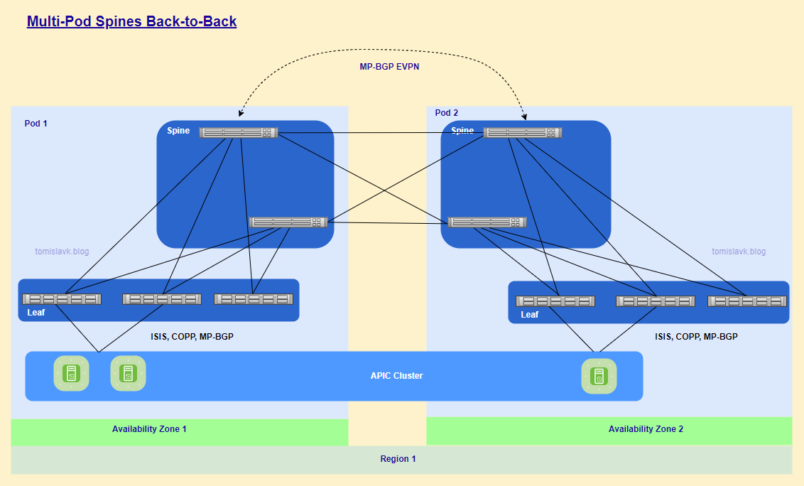
Figure 5. Cisco ACI Multi-Pod, pods connected directly via Spines.
The characteristics and use cases for Cisco ACI Multi-Pod with spine back-to-back interconnect are essentially the same as those for Cisco ACI Multi-Pod interconnected via an Inter-Pod Network (IPN). The primary distinction is the absence of an IPN. However, it is crucial to ensure direct connectivity between remote spines.
Advantages:
- Simplified Network Design: Eliminates the need for an Inter-Pod Network (IPN), simplifying the overall network design and reducing complexity.
- Reduced Latency:
Provides direct connectivity between remote spines, which can reduce latency compared to traversing an IPN. - Cost Efficiency:
Reduces the need for additional IPN devices and infrastructure, leading to cost savings. - Improved Performance:
Direct spine-to-spine connections can optimize traffic flow and improve overall network performance. - Enhanced Resiliency:
Offers redundant paths between Pods, enhancing network resiliency and fault tolerance.
6. Cisco ACI Multi-Site.
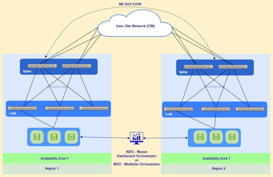
Figure 6. Cisco ACI Multi-Site managed by Nexus Dashboard Orchestrator.
Key Differences between Multi Site and Multi Pod deployment:
- Management: Multi-Pod uses a single APIC cluster, while Multi-Site uses multiple APIC clusters managed by NDO.
- Latency: Multi-Pod typically has lower latency between pods, whereas Multi-Site can handle higher latency across sites.
- Scalability: Multi-Site is better suited for large-scale, geographically dispersed deployments.
Main Characteristics:
- Geographical Flexibility: Supports the interconnection of geographically dispersed data centers, extending Layer 2 and Layer 3 connectivity between sites.
- Unified Policy Management: Utilizes the Nexus Dashboard Orchestrator (formerly Multi-Site Orchestrator) to manage and enforce policies across multiple sites.
- Fault Isolation: Each site operates with its own APIC cluster, ensuring fault isolation and independent control planes.
- Scalability: Allows for the integration of multiple ACI fabrics, providing scalability for large and distributed environments.
- Consistent Policy Enforcement: Ensures consistent policy enforcement across all interconnected sites, maintaining uniform security and network policies.
- Data Plane Communication: VXLAN and MP-BGP EVPN: Uses VXLAN for data-plane communication and MP-BGP EVPN for control-plane communication between sites.
Inter-Site Network (ISN) Requirements:
ACI fabrics are connected via ISN routed network which will be used for VxLAN communications between endpoints which they belong to different fabrics.
I would like to highlight that there is no latency limit between the different ACI fabrics part of the same Multi-Site domain.
The only latency considerations are:
- Up to 150 ms, RTT is the latency supported between the Nexus Dashboard cluster nodes where the Orchestrator service is enabled.
- Up to 500 msec RTT is the latency between each Nexus Dashboard Orchestrator node and the APIC controller nodes that are added to the Multi-Site domain. This means that the Multi-Site architecture has been designed from the ground up to be able to manage ACI fabrics that can be geographically dispersed around the world.
- No Need for Multicast.
- MTU between ISN routers and spines should be increases to minimum 1600 Bytes, in this case should be changed default MTU size 9000 Bytes in global configuration.
- IP connectivity can be achieved using OSPF, BGP or static routing.
Use Cases:
Centralized Data Center with Separate Availability Zones:
Allows for the creation of distinct availability zones within a centralized data center, enhancing fault isolation and resource management.
Disaster Recovery:
Facilitates disaster recovery by enabling data replication and failover between sites, ensuring business continuity in case of site failures.
Geographically Distributed Data Centers:
Supports the management of data centers spread across different cities, countries, or continents from a single pane of glass, simplifying provisioning, monitoring, and management.
Stretched Bridge Domain with Layer 2 Broadcast Extension:
Extends Layer 2 domains across sites, allowing for live VM migration and active/active high availability.
Stretched VRF with Inter-Site Contracts:
Enables consistent policy enforcement across sites by stretching VRFs and applying inter-site contracts.
Shared Services with Stretched Provider EPGs:
Allows shared services to be accessed across multiple sites using stretched Endpoint Groups (EPGs).
7. Multi-Pod - Multi-Site hybrid deployment.
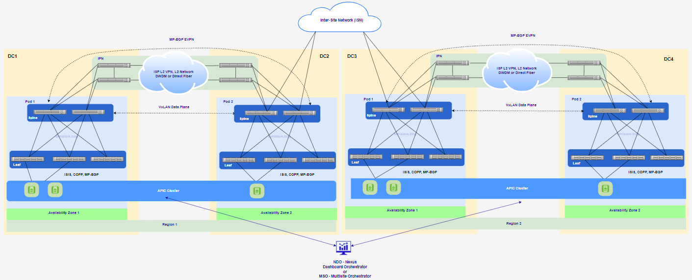 Figure 7. Extending Cisco ACI Multi-Pod to Multi-Site.
Using Cisco ACI Multi-Site and Multi-Pod as a single fabric offers several benefits, enhancing the overall network architecture. Here are some key advantages:
- Centralized Management:
Both Multi-Site and Multi-Pod architectures allow for centralized management through a single APIC cluster, simplifying policy enforcement and configuration. - Scalability:
Multi-Pod enables the expansion of a single ACI fabric across multiple locations without the need for separate fabrics, making it easier to scale the network.
Multi-Site allows for the interconnection of multiple ACI fabrics, providing scalability across geographically dispersed data centers. - Resiliency and Fault Isolation:
Multi-Pod architecture offers full resiliency at the network level across pods while maintaining a single fabric, ensuring minimal impact from failures.
Multi-Site architecture isolates failure domains between sites, enhancing overall network resiliency. - Disaster Recovery and Business Continuity:
Both architectures support disaster recovery by enabling data replication and failover between sites or pods, ensuring business continuity in case of site failures. - Consistent Policy Enforcement: Policies and configurations can be consistently applied across all sites and pods, ensuring uniform security and compliance.
- Operational Efficiency:
Centralized management and automation reduce administrative overhead and operational complexity, making it easier to manage large-scale networks.