Mastering Cisco ACI Physical Design

Let's dive into the world of Cisco ACI physical design. After all, we all know that without hardware, there is no cloud or networking.
Dive into the world of Clos Topology, a concept born from a 1952 paper by Charles Clos, a researcher at Bell Laboratories. His revolutionary ideas on multistage telephone switching systems have transcended time, now serving as the foundation for building highly scalable data centers with cost-effective switches. The Cisco ACI fabric is based on either a two-tier (spine and leaf switch) or three-tier (spine switch, tier-1 leaf switch, and tier-2 leaf switch) architecture. In a Cisco Application Centric Infrastructure (ACI), each of the leaf, Fabric Extenders and spine switches has different functions.
Leaf Switches
- Leaf switches are the ingress/egress points for traffic into and out of an ACI fabric.
- They connect directly to servers and other devices, facilitating rapid data transfer.
- Each leaf switch is linked to every spine switch, creating a mesh of high-bandwidth connections.
- This setup ensures that any data packet is only a couple of hops away from its destination, significantly reducing latency.
Fabric Extenders (FEX)
Fabric Extenders (FEX) in Cisco’s Application Centric Infrastructure (ACI) have several key functions:
- Port Extension - FEX extends the ports of a Nexus switch, acting as a remote line card. This allows for the use of more cost-effective devices with a reduced set of features that are connected to the Leaf Switches.
- Agile Connectivity - FEX offers agile connectivity for rack and blade servers and for converged fabric deployments. It delivers innovation to the data center, reduces total cost of ownership, and gains architectural flexibility.
- Configuration and Management - All management is done on the parent switch; there is no console/vty access on the FEX. This simplifies the management of the network infrastructure.
- Cisco ACI leaf switch models with -G or -Tin the product name, such as Cisco Nexus N9K-C9348GC-FXP, N9K-C93108TC-FX, N9K-C93108TC-FX-24, N9K-C93108TC-EX, N9K-C93108TC-EX-24, N9K-C93216TC-FX2, and N9K-93108TC-FX3P.
Discover the steps to configure Fabric Extenders (FEX) in Cisco ACI in Cisco comprehensive guide available here.
Spine Switches
Spine switches are Clos intermediary switches that have a number of key functions:
- They are responsible for high-capacity data transmission across the network.
- They ensure that data packets travel efficiently from one leaf switch to another.
- The spine layer is crucial for maintaining the performance of the network as it scales, providing a robust framework that can handle increasing data demands without bottlenecks.
- Spine switches interconnect all leaf switches in a full-mesh topology.
Together, they create an architecture that is highly standardized across deployments. This design allows for a highly scalable and efficient network infrastructure.
Two-Tier or Multi-Tier Design?
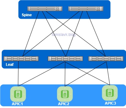
Below Figure 1 illustrates the necessary components and cabling for an two-tier ACI fabric. It’s important to note that no cables should be connected between ACI leaf switches, as this is characteristic of Clos network design. Similarly, cross-cabling ACI spines will lead to the disabling of the cross-connected ports. The topology depicts a full mesh of cabling between the spine and leaf layers. However, it’s important to note that while the Spine-Leaf architecture can be implemented without ACI, with the switches working in NX-OS mode. I would like to highlight that ASICs are different for Leaf and Spine switches, so a switch like the Nexus N9K-93180YC-EX cannot run as Spine switches.

Figure 1 Two-Tier Topology Spine-Leaf classic interconnect between leaf and spine switches
In summary, I would like to recommend to check switch compatibility on the links below:
- Cisco Nexus 9300 1/10GBaseT Switches
- Cisco Nexus 9300 1/10/25/40/50/100GE Fiber Switches
- Cisco Nexus 9300 40/100 GE Switches
- Cisco Nexus 9300 400 GE Switches
- Cisco Nexus 9300 ACI Fixed Spine Switches Data Sheet
If you plan to use Cisco Nexus modular switches for Cisco ACI fabric technical details you can find on below links:
- Cisco Nexus 9500 Series Switches Data Sheet
- Nexus 9500 Chassis Comparison
- Nexus 9800 Compare Models
- Nexus 9800 Line Cards comparison
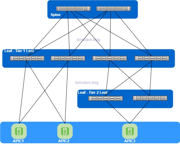
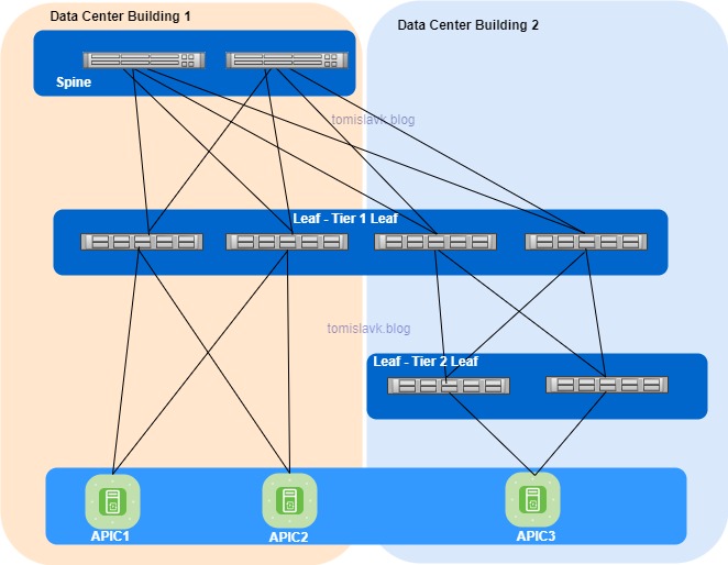
Starting from Cisco ACI 4.1, the fabric also supports a multi-tier (three-tiers) topology. This includes two tiers of leaf switches, allowing for vertical expansion of the Cisco ACI fabric. This is particularly useful for migrating a traditional three-tier architecture (core-aggregation-access), a common design model for many enterprise networks. The ACI Multi-Tier is a beneficial solution for data centers aiming to reduce inter-row cabling and have low-bandwidth needs for top-of-rack switches. In this setup, Tier 1 leaf switches are placed at the end of each row, while Tier 2 leaf switches are positioned at the top of each rack. This strategy is particularly effective in managing cables and meeting bandwidth requirements.

Figure 2 Multi -Tier Topology Spine- Tier 1 Leaf and Tier 2 Leaf

Figure 3 Multi -Tier Topology Spine- Tier 1 Leaf and Tier 2 Leaf option between two data center buildings
The topology requirements may include various models of spine and leaf switches, please check below:
-
Spine: EX/FX/C/GX/GX2 spines (For example, Cisco Nexus 9332C, 9316D-GX, 9348D-GX2A, 9408 and 9500 with EX/FX/GX linecards).
-
Tier-1 Leaf: EX/FX/FX2/FX3/GX/GX2 except Cisco Nexus 93180LC-EX.
-
Tier-2 All EX/FX/FX2/FX3/GX/GX2.
In the scenario where server access is at 1G and there is not need for high bandwidth, it’s a viable choice to use the Cisco Nexus 93180FX3 or Nexus 9364C-GX as the tier-1 leaf and the Cisco Nexus 9348FXP as the tier-2 leaf.
Before you start to build and design a multi-tier topology in a Cisco ACI environment, please take into account the following:
1.Fabric Port Configuration: All inter-switch connections must be configured as fabric ports. This includes the connections between Tier-2 leaf switch fabric ports and Tier-1 leaf switch fabric ports.
2.Tier-2 Leaf Switch Connectivity: A Tier-2 leaf switch has the capability to connect to more than two Tier-1 leaf switches. This is in contrast to a traditional double-sided vPC design, which only supports two upstream switches. The maximum number of ECMP links supported by a Tier-2 leaf switch to a Tier-1 leaf switch is 18.
3.Endpoint Group (EPG) and Layer 3 Outside (L3Out) Connections: EPGs, L3Outs, Cisco APICs, or Fabric Extenders (FEX) can be connected to either Tier-1 or Tier-2 leaf switches.
4.Tier-1 Leaf Switch Connections: Tier-1 leaf switches can have both hosts and Tier-2 leaf switches connected to them.
5.Switch Tier Transition: Transitioning from a Tier-1 to a Tier-2 leaf switch (and vice versa) requires decommissioning and recommissioning the switch.
6.Compatibility with Cisco ACI Multi-Pod and Multi-Site: Multi-tier architectures are compatible with both Cisco ACI Multi-Pod and Cisco ACI Multi-Site.
7.Tier-2 Leaf Switch Connectivity Limitations: Tier-2 leaf switches cannot be connected to remote leaf switches (Tier-1 leaf switches).
8.Scale Considerations: The combined number of Tier-1 and Tier-2 leaf switches must not exceed the maximum number of leaf switches validated for a given release (400 per pod; 500 per Cisco ACI Multi-Pod as of Cisco ACI release 6.0(1)).
Reference for Cisco ACI Multi-tier Architecture.
Fabric Port
In Cisco's Application Centric Infrastructure (ACI), a fabric port is a type of port that is used for uplink connectivity within the fabric. These ports are typically used to connect different switches within the ACI fabric. For example, in a multi-tier topology, all switch-to-switch links must be configured as fabric ports. This includes the connections between Tier-2 leaf switch fabric ports and Tier-1 leaf switch fabric ports.
Fiber optics modules
Don't forget that based on specific switch model and uplinks design you will need to choose proper optical modules. All details about compatibility matrix for Cisco Optics and devices you can find on below links:
If you struggling or you have some doubts about compatibility between switches and optical modules SFP SFP+ QSFPs I would like to recommend:
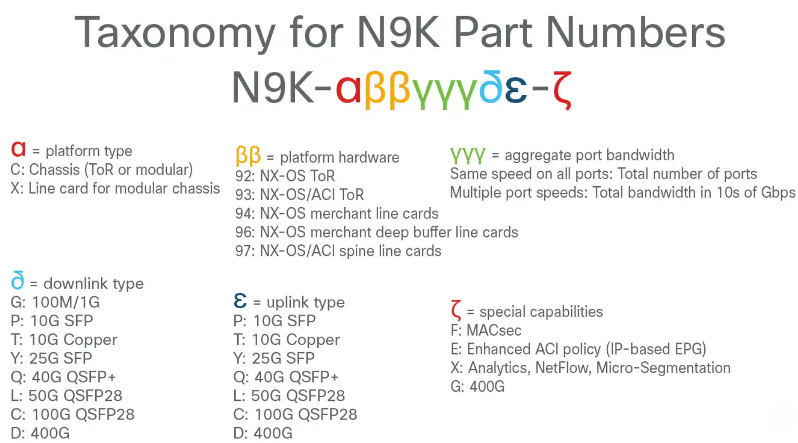
Taxonomy for Cisco Nexus 9000 Series Part Numbers
For a comprehensive understanding and decoding of all Nexus Part Numbers names, kindly refer to Figure 4.

Figure 4 Cheet-sheet for decoding Cisco Nexus 9000 Series Part Numbers