Five easy steps to configure static VxLAN Part 4

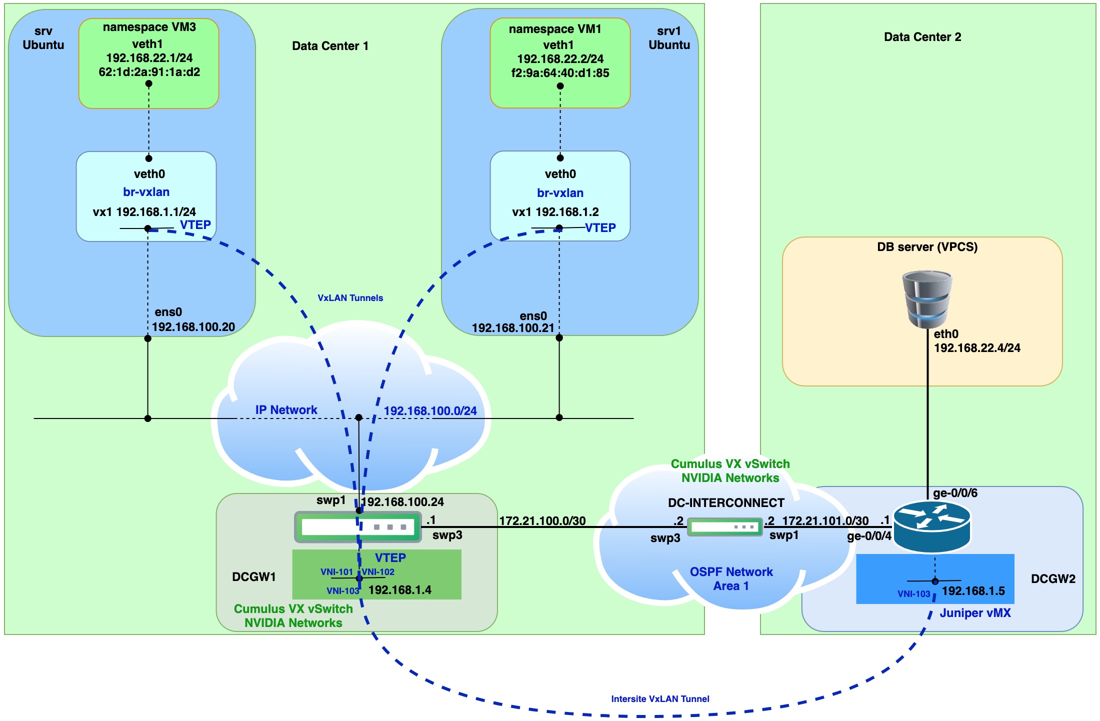
Part 4 final countdown with static VxLAN. In this post I will cover the case when we need to extend L2 domain between Data centers. According to this VxLAN tunnel will be established between two DC gateways and DC gateways will represent VTEPs.
Data center gateways will be simulated with Cumulus Linux VX vSwitch and Juniper vMX virtual router. This time I will skip installation and configuration of the following:
- namespaces for simulation of VM1 and VM3
- Download VPCS and configuration
- Configuration of VxLAN tunnels from srv and srv1 to Cumulus VX switch as it will be the same like in Part 3.

Virtual router, switch and linux host machines:
| VM name | OS Version | Extra installed SW |
|---|---|---|
| srv | Ubuntu 20.04 | bridge-utils |
| srv1 | Ubuntu 20.04 | bridge-utils |
| virtual switch | Cumulus Linux 4.4.1 VX (Nvidia) | |
| virtual router | Juniper vMX JUNOS 18.4R1.8 |
Step 1. Configure interfaces on dcgw1 and dcgw2
On dcgw1 (Cumulus Linux) configure interface for OSPF peering with dc-interconnect router
net add interface swp3 ip address 172.21.100.1/30
add loopback which will be used for VTEP termination point.
net add loopback lo ip address 192.168.1.4/32
Above we should repeat for dcgw2 (Juniper vMX)
set interfaces xe-0/0/4 unit 0 family inet address 172.21.101.1/30
add loopback which will be used for VTEP termination point.
set interfaces lo0 unit 5 family inet address 192.168.1.5/32
Step 2. Configure dc-interconnect L3 switch interfaces(Cumulus Linux VX)
Add loopback
net add loopback lo ip address 2.2.2.2/32
Add interface for peering with dcgw1
net add interface swp3 ip address 172.21.100.2/30
Add interface for peering with dcgw2
net add interface swp1 ip address 172.21.101.2/30
Step 3. Configuration of OSPF peering
Apply on dcgw1.
Set router ID.
net add ospf router-id 192.168.1.4
Add specific networks to OSPF.
net add ospf network 192.168.1.4/32 area 1
net add ospf network 172.21.100.0/30 area 1
Change network type on link between dcgw1 and dc-interconnect.
net add interface swp3 ospf network point-to-point
On unnecessary interfaces stop sending OSPF messages.
net add ospf passive-interface swp1
net add ospf passive-interface swp2
net add ospf passive-interface swp4
net add ospf passive-interface swp5
net add ospf passive-interface swp6
net add ospf passive-interface swp7
Apply on dc-interconnect.
Set router ID.
net add ospf router-id 2.2.2.2
Add specific networks to OSPF.
net add ospf network 2.2.2.2/32 area 1
net add ospf network 172.21.100.0/30 area 1
net add ospf network 172.21.101.0/30 area 1
Change network type on links between dc-interconnect dcgw1 and dcgw2.
net add interface swp3 ospf network point-to-point
net add interface swp1 ospf network point-to-point
On unnecessary interfaces stop sending OSPF messages.
net add ospf passive-interface swp2
net add ospf passive-interface swp4
net add ospf passive-interface swp5
net add ospf passive-interface swp6
net add ospf passive-interface swp67
Apply on dcgw2.
Set router ID.
set routing-options router-id 192.168.1.5
Change network type on links between dc-interconnect and dcgw2 and enable OSPF on xe-0/0/4 (172.21.101.0/30).
set protocols ospf area 0.0.0.1 interface xe-0/0/4.0 interface-type p2p
Enable OSPF on loopback
set protocols ospf area 0.0.0.1 interface lo0.5
Check OSPF routes on dc-interconnect L3 switch.

Step 4. Add static VxLAN tunnels between dcgw1 and dcgw2
Apply on dcgw1.
Create VxLAN tunnel interface.
net add vxlan vni-103 vxlan id 103
Add vni-103 to specific bridge.
net add bridge br-22 ports vni-103
Configure Loopback primary address for VTEP source.
net add vxlan vni-103 vxlan local-tunnelip 192.168.1.4
Configure remote VTEP on dcgw2.
net add vxlan vni-103 vxlan remoteip 192.168.1.5
Apply on dcgw2.
Create bridge domain.
set bridge-domains br-vl22 vlan-id 22
set bridge-domains br-vl22 vxlan vni 103
Enable “ingress-node-replication” this will handle incoming broadcast, unknown unicast, or multicast (BUM) traffic.
set bridge-domains br-vl22 vxlan ingress-node-replication
Configure Loopback lo0.5 for VTEP source.
set switch-options vtep-source-interface lo0.5
Configure remote VTEP on dcgw1.
set switch-options remote-vtep-list 192.168.1.4
Step 5. Connectivity check
Run PING command from VM1, VM3 and DB server (VPCS)

Issue ping from VM3 (namespace)
sudo ip netns exec vm3 ping 192.168.22.4 -- > remote IP on DB server.


Issue ping from VM1 (namespace)
sudo ip netns exec vm1 ping 192.168.22.4 -- > remote IP on DB server.


From the capture you can see that two VxLAN tunnels were used for interconnection with Cumulus VX virtual switch. Both tunnels landed on to one bridge on Cumulus VX virtual switch. That way we achieve communication between two VMs and DB server (VPCS).
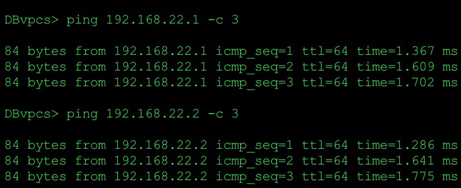
Issue ping from DB server (VPCS) to check connectivity with VM1 and VM3

Based on the ping and packet captures we can conclude that we have L2 connectivity between two data centers. It means that we build overlay network on top of classical L3 network connectivity.
Part 1 Static VxLAN between Ubuntu hosts
Part 2 Static VxLAN between Ubuntu and Cumulus VX vSwicth
Part 3 Static VxLAN between Ubuntu Hosts and Cumulus VX vSwitch DC Gateway