At this point, we understand:
- Why EVPN exists
- What EVPN actually is
- How EVPN differs from VXLAN
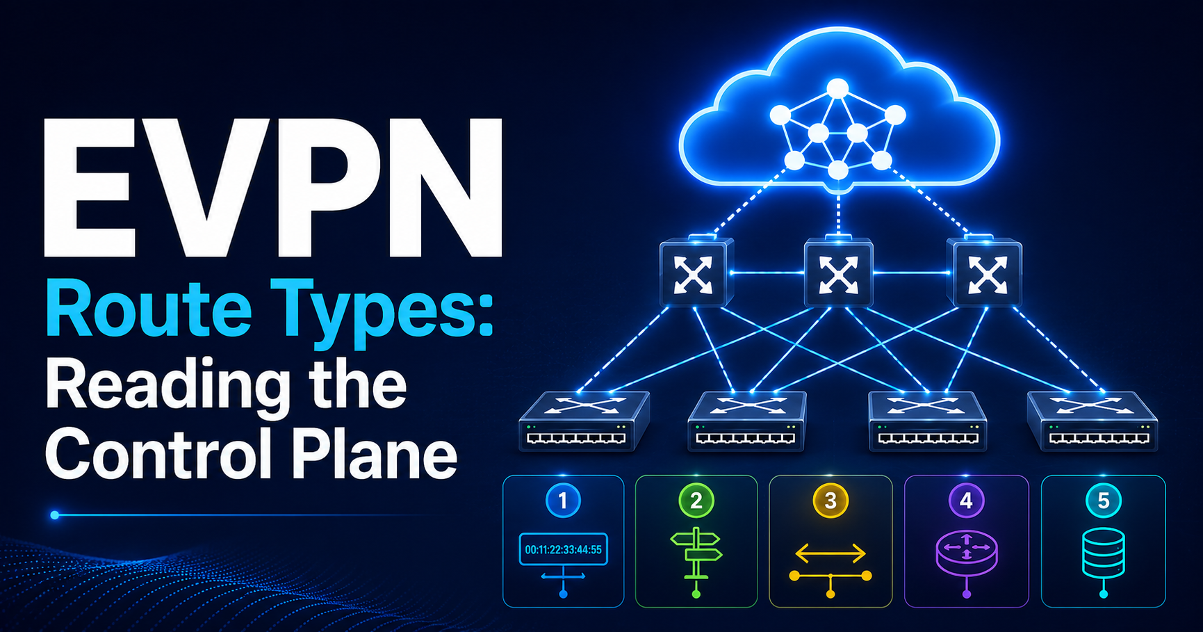
- The role of Route Types 1–5
Now we arrive at the area where many EVPN deployments either become elegant or become operationally painful:
Multi-homing.
This is where EVPN starts delivering capabilities that traditional Ethernet architectures struggle to provide.
It’s also where engineers often discover that many assumptions carried over from STP, MLAG, and classic data center designs no longer apply.
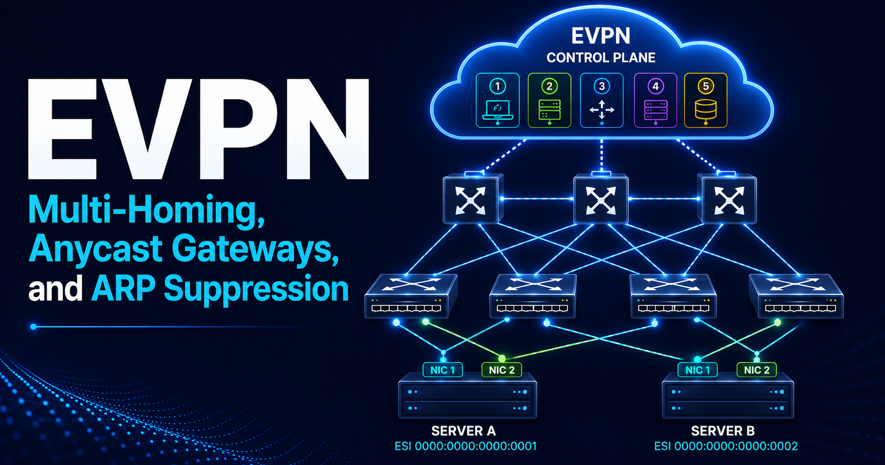
EVPN Multi-Homing Deep Dive
If I had to identify one feature that convinced many architects to adopt EVPN, it would be EVPN multi-homing.
Not because it is flashy.
Because it solves a very old networking problem in a much cleaner way.
The Traditional Problem
Every data center engineer wants:
Redundancy
+
Load Sharing
+
Fast Convergence
+
No Loops
Traditional Ethernet has historically struggled to deliver all four simultaneously.
Option 1: Spanning Tree
You get:
Redundancy
+
Loop Prevention
But sacrifice:
Blocked Links
Suboptimal Paths
Option 2: MLAG
You get:
Active/Active Uplinks
Fast Convergence
But introduce:
Peer Links
State Synchronization
Split-Brain Protection
Vendor Dependencies
MLAG improved the situation dramatically.
Yet it never fully solved it.
Why MLAG Alone Is Not Enough
Many engineers assume EVPN multi-homing is simply MLAG with a different name.
It is not.
MLAG typically requires:
Leaf1 <------ Peer Link ------> Leaf2
The two switches must exchange:
- MAC tables
- ARP entries
- State information
- Failure information
Operationally, this creates a dependency.
The switches are no longer fully independent.
This becomes increasingly problematic as fabrics scale.
EVPN’s Different Approach
Instead of synchronizing state through proprietary peer-link mechanisms, EVPN distributes state through BGP.
Think about what this means.
Instead of:
Switch A
    |
Peer Link
    |
Switch B
We now have:
Leaf1
   \
    EVPN
   /
Leaf2
The control plane becomes distributed.
The dependency shifts from proprietary synchronization toward standardized route advertisements.
Ethernet Segments
The foundation of EVPN multi-homing is the Ethernet Segment.
An Ethernet Segment simply represents:
The links connecting a server or switch to one or more EVPN leafs.
Example:
         Server
        /      \
     Leaf1    Leaf2
This connection is represented as a single Ethernet Segment.
Ethernet Segment Identifier (ESI)
Every Ethernet Segment receives a unique identifier.
Example:
ESI
00:00:00:00:00:00:00:00:00:01
Think of the ESI as a name that must be unique across the EVPN domain.
Whenever a leaf advertises:
ESI 0001
other VTEPs immediately understand:
These devices belong to the same multi-homed segment.
Without an ESI, EVPN cannot determine that multiple attachment points belong to the same multi-homed segment.
Why ESI Matters
Imagine:
Server A
 |
 +-- Leaf1
 |
 +-- Leaf2
Remote VTEPs see:
Leaf1 advertises MAC
Leaf2 advertises MAC
Without ESI information:
Looks like duplicate MACs
With ESI:
Looks like multi-homing
Huge difference.
Route Types Involved
Multi-homing relies heavily on:
Type 1
Ethernet Auto-Discovery (per-ES and per-EVI)
Type 2
MAC/IP Advertisement, carrying the ESI of the segment
Type 4
Ethernet Segment Route, used for DF election
Together they allow:
- Leafs on the same segment to find each other and elect a DF (Type 4)
- Remote VTEPs to learn segment membership and load-balance (Type 1 + ESI in Type 2)
Remote VTEPs never import Type 4 routes.
Designated Forwarder (DF)
One of the most misunderstood concepts in EVPN.
Why DF Exists
Consider BUM traffic.
Broadcast
Unknown Unicast
Multicast
If both leafs forward the same traffic:
Duplicate Frames
Bad.
If neither forwards:
Traffic Loss
Also bad.
Someone must be responsible.
That responsibility belongs to the Designated Forwarder.
DF Election
EVPN performs DF election automatically.
Example:
Leaf1
Leaf2
One becomes:
DF
The other becomes:
Non-DF
This decision occurs through EVPN signaling.
No proprietary protocol required.
Type 4 routes let leafs on the same Ethernet Segment find each other.
Only those leafs import them. The ES-Import Route Target takes care of that.
The default election (RFC 7432) works like this:
1. Sort the originating IPs from the Type 4 routes (including its own), lowest first
2. Number them 0 to N-1
3. For VLAN V, the DF is leaf number (V mod N)
   (VLAN-aware bundle: V = lowest VLAN in the bundle)
So each VLAN can have a different DF.
Some platforms use other methods, such as DF preference.
Operational Reality
A common misconception:
“The DF forwards everything.”
In all-active mode, this is incorrect.
The DF only controls:
BUM traffic from the fabric toward the segment
Traffic from the host, and known unicast, can use any leaf on the segment.
In single-active mode, it is true: only the DF forwards traffic.
Understanding this distinction prevents countless troubleshooting mistakes.
Aliasing
Aliasing is one of EVPN’s most powerful features.
Unfortunately, many engineers never fully understand it.
Type 1 routes have two subtypes:
- Per-ES (Ethernet Segment): used for mass withdrawal during failure
- Per-EVI (EVPN Instance): used for aliasing (all-active) and backup paths (single-active)
Aliasing specifically relies on the per-EVI subtype.
Traditional Thinking
Imagine:
Server
 |
 +-- Leaf1
 |
 +-- Leaf2
The server’s LAG sends each flow over one link.
So only Leaf1 may learn the server’s MAC:
Leaf1 advertises Type 2 for the MAC
Leaf2 never sees it
Remote VTEPs then send all traffic to Leaf1.
Leaf2 sits idle.
EVPN Aliasing
Both leafs advertise per-EVI Type 1 routes for the same ESI.
Remote VTEPs see the ESI in the Type 2 route and know:
Leaf1 available

Leaf2 available
Traffic is load-balanced across both leafs.
Even though only Leaf1 advertised the MAC.
Faster failover is a bonus: the second path is already in use.
Backup Path Behavior
In single-active mode, only the DF forwards traffic.
Per-EVI Type 1 routes tell remote VTEPs where the backup is:
Pre-installed backup forwarding information.
Fast Convergence
A key design objective of EVPN is minimizing control-plane churn during failures.
When a segment link fails, the leaf withdraws one route:
Per-ES Type 1 Route
Remote VTEPs drop that leaf for every MAC on the segment at once.
When a whole leaf fails, it cannot withdraw anything.
Remote VTEPs notice because its VTEP address disappears from the underlay.
This is fundamentally different from flood-and-learn designs.
Common Multi-Homing Mistakes
After reviewing many EVPN deployments, certain mistakes appear repeatedly.
Mistake 1
Inconsistent ESI Configuration
Example:
Leaf1
ESI 0001

Leaf2
ESI 0002
EVPN no longer sees a shared segment.
Symptoms:
- Duplicate MACs
- DF problems
- Traffic asymmetry
Mistake 2
Assuming EVPN Multi-Homing Works Like MLAG
Many troubleshooting approaches fail because engineers apply MLAG logic.
EVPN behaves differently.
Think:
BGP signaling
not
Peer-link synchronization
Mistake 3
Ignoring Failure Testing
Many deployments validate:
Everything Up
Few validate:
Leaf Failure
Link Failure
DF Failure
ESI Failure
This creates surprises later.
Common Troubleshooting Symptoms
When multi-homing breaks:
Typical symptoms include:
MAC Flapping
Host appears on Leaf1

Then Leaf2

Then Leaf1
Usually ESI or signaling issues.
Duplicate Traffic
Often indicates:
DF election problem
For example, missing Type 4 routes: each leaf elects itself DF.
Blackholing
Common causes:
Missing Type 1

Leaf lost its uplinks, host links still up

Aliasing failure
EVPN and VXLAN Integration
Now let’s connect the control plane to the forwarding plane.
This is where EVPN and VXLAN work together.
Control Plane vs Data Plane
A simple mental model:
EVPN
Answers:
Where is the destination?
VXLAN
Answers:
How do I get there?
VTEPs
The central component is the:
VXLAN Tunnel Endpoint (VTEP)
A VTEP performs:
Encapsulation

Decapsulation

Forwarding
Every leaf typically acts as a VTEP.
Example Fabric
Host A
 |
Leaf1 (VTEP)
 |
Spine
 |
Leaf2 (VTEP)
 |
Host B
Host Attachment
Host A appears.
Leaf1 learns:
MAC

IP

VLAN
Leaf1 generates:
Type 2 Route
EVPN distributes this information.
Endpoint Discovery
Remote VTEPs learn:
Host A
MAC aa:aa
IP 10.10.10.10

Reachable via Leaf1
No flooding required.
Host A → Host B Packet Walk
Let’s walk through the complete forwarding process.
Step 1
Host A sends frame.
Dst MAC = Host B
Step 2
Leaf1 checks its MAC table (programmed from EVPN Type 2 routes).
Finds:
Host B reachable through Leaf2
Step 3
Leaf1 performs VXLAN encapsulation.
Outer Header:
Src VTEP = Leaf1

Dst VTEP = Leaf2

VNI = 10010
Inner Frame:
Original Ethernet Packet
Step 4
Underlay forwards packet.
Spines only see:
IP Packet
Nothing about tenants.
Nothing about MAC addresses.
Nothing about VLANs.
Step 5
Leaf2 receives packet.
Removes VXLAN header.
Forwards original Ethernet frame.
Step 6
Host B receives traffic.
Communication complete.
Important Insight
The spine never learns:
Tenant

MAC

VLAN

Host state
Spines only transport packets.
This separation is one reason EVPN fabrics scale so effectively.
One caveat: spines are often route reflectors or eBGP EVPN peers.
Then they do carry EVPN routes in BGP. They just never install them.
Distributed Anycast Gateway
If EVPN multi-homing is the most powerful Layer 2 feature, Anycast Gateway is arguably the most important Layer 3 feature.
Traditional Gateway Problem
Historically:
Default Gateway
lived in one place.
Example:
Core Switch
Traffic path:
Host

↓

Core

↓

Destination
As workloads moved, traffic often became suboptimal.
Modern Requirement
In modern data centers:
The gateway should exist:
Everywhere
This is the Anycast Gateway concept.
Anycast Gateway Design
Every participating leaf is configured with:
Same virtual gateway IP

Same virtual MAC (VMAC)
for that subnet.
This requires explicit configuration or vendor-specific automation.
Example:
10.10.10.1

02:00:00:00:00:01
across all leafs.
What This Achieves
Every host believes:
Gateway is local
because it is.
The gateway exists on every VTEP.
Why First-Hop Mobility Matters
Imagine:
VM Migration
from:
Leaf1 → Leaf2
Without Anycast Gateway:
Gateway stays on the core

Traffic hairpins back to it
With Anycast Gateway:
Same gateway IP and MAC on the new leaf

Routing stays local
Migration becomes seamless.
Host Mobility Event
Example:
VM moves
New leaf advertises:
Updated Type 2 Route (MAC Mobility sequence number + 1)
Remote VTEPs update forwarding.
Gateway remains unchanged.
No default gateway reconfiguration required.
Advantages
Anycast Gateway provides:
Optimal Routing
Traffic routed locally.
Better Scale
No centralized bottleneck.
Faster Mobility
VMs move seamlessly.
Better East-West Performance
Particularly important in modern application architectures.
Failure Scenarios
Suppose:
Leaf1 fails
Host attached elsewhere.
Gateway still exists throughout fabric.
No dependency on a single gateway location.
This dramatically improves resiliency.
ARP Suppression Explained Properly
ARP suppression is perhaps the most misunderstood EVPN feature.
Many engineers can configure it.
Few can explain how it actually works.
Traditional ARP Behavior
Host wants:
10.10.10.20
But only knows:
IP Address
Host sends:
ARP Request
Broadcast.
Traditional Ethernet Response
ARP floods across VLAN.
Every device receives:
Who owns 10.10.10.20?
Most ignore it.
One responds.
At scale this becomes inefficient.
EVPN Approach
Type 2 routes advertise:
MAC

IP
together.
Example:
10.10.10.20

MAC bb:bb
Now the local VTEP already knows the answer.
Proxy Response
Instead of flooding:
The VTEP replies locally.
ARP Request

↓

Proxy Response

↓

No Flooding
This is ARP suppression.
Scale Benefits
Large environments can reduce:
- Broadcast traffic
- BUM replication load
- Host CPU spent on unneeded ARPs
dramatically.
In some environments the reduction is enormous.
Operational Limitations
ARP suppression is not magic.
It depends on:
Accurate MAC+IP Type 2 Routes
No Type 2 route:
No ARP suppression
When no Type 2 route exists, the VTEP falls back to flooding the ARP request across the fabric — standard behavior, but the suppression benefit is lost.
Common Troubleshooting Scenario
Host cannot resolve neighbor.
Check:
Is MAC/IP binding present?

Is Type 2 route present?

Is local ARP suppression database populated?
Often the issue is not ARP suppression itself.
The issue is missing endpoint advertisements.
Practical Troubleshooting Sequence
When ARP suppression appears broken:
Verify:
Step 1
EVPN Type 2 Route Exists
Step 2
MAC Present
Step 3
IP Present
Step 4
ARP Suppression Database Populated
Step 5
VNI Correct
Most problems are discovered within those five checks.
Key Takeaways
Before moving into EVPN design and architecture, every engineer should remember:
- EVPN multi-homing is not MLAG.
- ESI identifies multi-homed segments.
- Type 1 and Type 4 routes enable multi-homing.
- DF election controls BUM forwarding behavior.
- Aliasing load-balances traffic across all leafs on a segment. Per-ES route withdrawal gives fast failover.
- EVPN provides the control plane; VXLAN provides the data plane.
- VTEPs encapsulate and decapsulate VXLAN traffic.
- Anycast Gateway places the default gateway everywhere.
- Host mobility relies on Type 2 route updates carrying the MAC Mobility extended community, which sequences endpoint location changes.
- ARP suppression works because EVPN distributes MAC/IP bindings through the control plane.
- Most ARP suppression issues are actually Type 2 route issues.
- Spines transport packets and hold no tenant state in hardware, even when they relay EVPN routes.
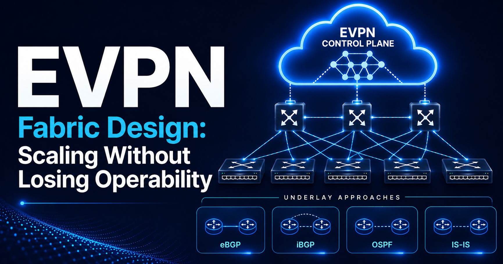
In Part 4, we will cover EVPN Design Considerations, including underlay architecture (eBGP vs iBGP vs OSPF vs IS-IS), route reflectors, spine participation, tenant and VRF design, VNI allocation strategies, route target planning, scaling considerations, and the architectural decisions that separate small EVPN deployments from large production-ready fabrics.