At some point every EVPN project reaches a crossroads.
The technology works.
The lab validates.
Hosts communicate.
VXLAN tunnels come up.
Route Type 2 advertisements appear.
The proof of concept succeeds.
Then the real question emerges:
“Will this design still work three years from now?”
This is where architecture becomes more important than configuration.
Most EVPN outages I have seen were not caused by EVPN itself.
They were caused by design decisions made months or years earlier:
- Underlay choices
- Route reflector placement
- Poor VNI allocation
- Inconsistent tenant models
- Route-target sprawl
- Scale assumptions that proved incorrect
The purpose of this section is not to tell you there is only one correct design.
There isn’t.
The purpose is to explain the tradeoffs experienced architects consider before deploying EVPN into production.
Design Philosophy Before Design Details
Before discussing protocols and topologies, establish the correct mindset.
A successful EVPN fabric should be:
Predictable
Engineers should understand where routes originate and where they go.
Repeatable
Adding a rack should follow the same process as adding the previous rack.
Observable
Operations teams should be able to troubleshoot quickly.
Scalable
Growth should not require architectural redesign.
Failure-Tolerant
Failures should be expected, tested, and survivable.
The best EVPN design is usually the simplest one that meets requirements.
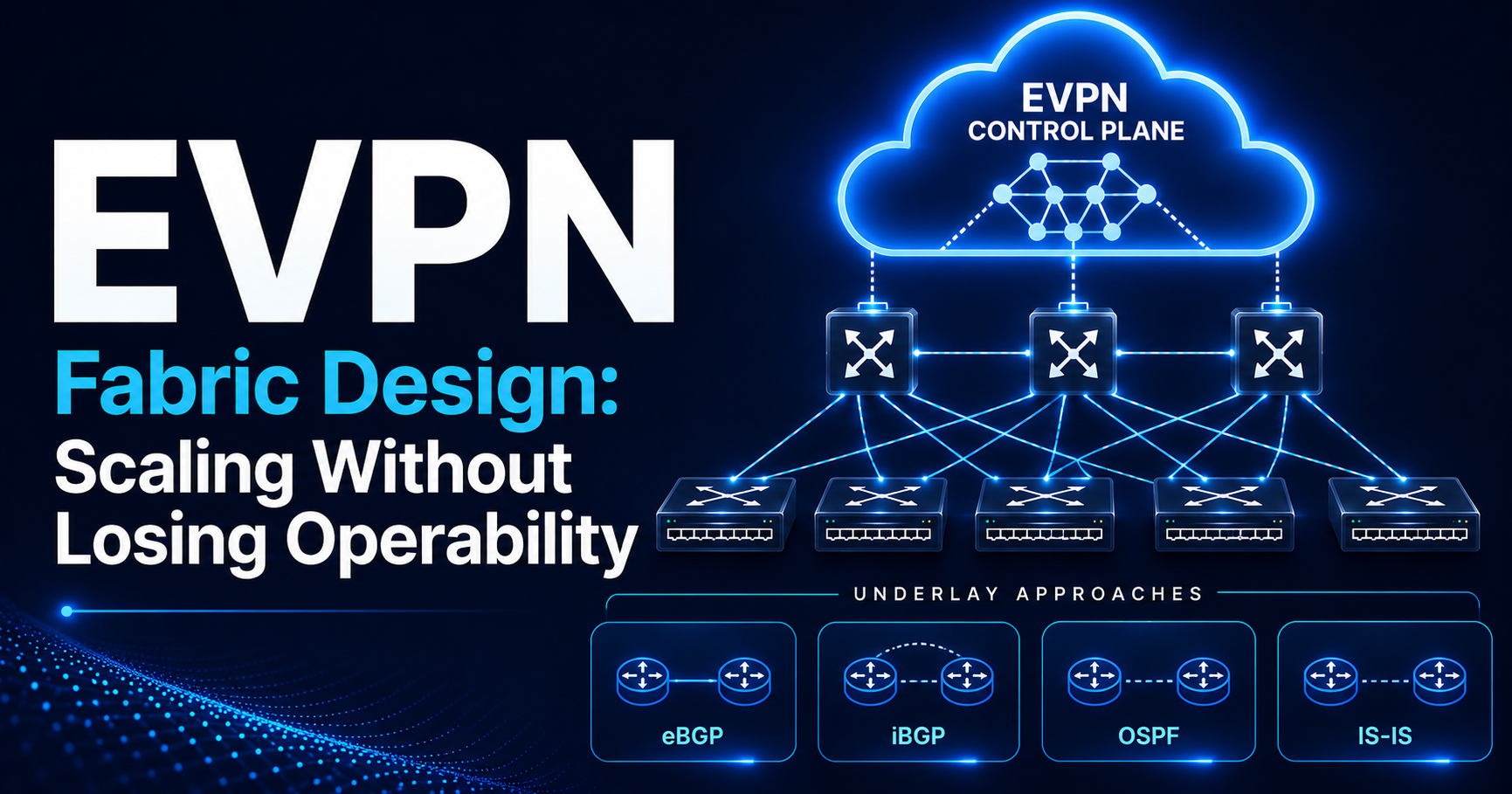
Underlay Design
One of the most common mistakes engineers make is spending months discussing EVPN while barely discussing the underlay.
The reality is:
EVPN cannot compensate for a poor underlay.
If the underlay is unstable, the overlay will be unstable.
Every EVPN route eventually depends on IP reachability between VTEPs.
Underlay Objectives
The underlay should provide:
IP Reachability

Fast Convergence

ECMP

Jumbo MTU (VXLAN adds 50 bytes)

Operational Simplicity

Predictable Failure Behavior

BFD Support
Notice what is absent:
VLAN Extension

Tenant Awareness

MAC Learning
In most EVPN VXLAN designs, the underlay should remain unaware of overlay services.
eBGP Underlay
Over the last decade, eBGP has become the dominant choice for modern leaf-spine fabrics.
Example:
Leaf1 ---- Spine1

Leaf1 ---- Spine2

Leaf2 ---- Spine1

Leaf2 ---- Spine2
Every connection:
eBGP
Why eBGP Became Popular
Historically, engineers associated eBGP with:
Internet Routing
Modern fabrics changed that perception.
eBGP provides:
Simple Neighbor Relationships
Every link becomes a routing boundary.
Fast Failure Detection
When a directly connected link goes down, the session drops at once.
For other failures, use BFD.
Built-In Loop Prevention
AS path validation helps prevent mistakes.
Operational Clarity
When something breaks, troubleshooting tends to be straightforward.
eBGP Advantages
Excellent Scale
Thousands of routes are routine.
Strong Failure Isolation
Problems typically remain localized.
Vendor Neutrality
Widely implemented and understood.
Natural ECMP Support
Ideal for Clos fabrics.
eBGP Challenges
ASN Management
Every device requires an ASN strategy.
- ASN exhaustion risk in large fabrics if private ASN ranges are not carefully planned.
Policy Complexity
Large environments may require careful policy design.
Learning Curve
Teams coming from OSPF-only environments often need time to adapt.
Practical Guidance
If building a new data center fabric today:
eBGP is usually the first option I evaluate.
Not because it is fashionable.
Because it aligns well with modern leaf-spine architectures.
iBGP Underlay
Some organizations choose iBGP throughout the underlay.
Example:
All devices

AS 65000
Advantages:
- Consistent ASN
- Simplified numbering
- Familiarity for some teams
Challenges:
- Next-hop handling requires next-hop-self configuration or IGP for VTEP reachability
- Route reflector requirements
- Additional design complexity
For most greenfield deployments, iBGP underlays are less common than eBGP.
OSPF Underlay
Many enterprise engineers feel comfortable with OSPF.
For good reason.
OSPF is mature and well understood.
OSPF Strengths
Familiar Operations
Many teams already support OSPF.
Strong Vendor Support
Universally available.
Stable Convergence
Reliable and predictable.
OSPF Challenges
Area Design
Large fabrics introduce area considerations.
LSA Scaling
Large environments may generate substantial LSA flooding, particularly if adjacency instability occurs in a large flat area design.
Complexity at Scale
Clos fabrics often align more naturally with BGP.
IS-IS Underlay
Service providers and large-scale operators frequently favor IS-IS.
IS-IS Advantages
Highly Scalable
Excellent for large environments.
Protocol Efficiency
Designed for large topologies.
Popular in SP Networks
Extensive operational experience exists.
IS-IS Challenges
Enterprise Familiarity
Fewer enterprise engineers know IS-IS deeply.
Operational Skill Gap
Training requirements may be higher.
Choosing an Underlay
A practical summary:
| Underlay | Typical Environment |
|---|---|
| eBGP | Modern leaf-spine fabrics |
| OSPF | Enterprise environments |
| IS-IS | Service providers and large-scale operators |
| iBGP | Specialized designs |
The best protocol is usually the one your organization can operate effectively.
Overlay Design
Now we move to EVPN itself.
The overlay distributes:
MACs

IPs

VNIs

VRFs

Tenant Reachability
The most important question becomes:
How will EVPN routes be distributed?
Route Reflectors
This applies to iBGP overlays.
iBGP requires a full mesh between all leafs.
In large fabrics, that is impractical.
Example:
50 leaf switches.
Full mesh requires:
1225 BGP Sessions
Not ideal.
Route Reflectors Solve This
Instead:
Leafs
   |
   |
Route Reflectors
Every leaf peers only with the RRs.
What About eBGP Overlays?
With an eBGP overlay, no RRs are needed.
Spines pass EVPN routes on to other leafs, as eBGP does by default.
Two things must be right:
Next hop unchanged

Spines keep all EVPN routes
The next hop must stay the original VTEP.
Spines must keep routes even for route targets they don’t import.
Common RR Locations
Dedicated Route Reflectors
Most scalable.
Example:
RR1
RR2
Dedicated virtual or physical nodes.
Spine-Based Route Reflectors
Very common.
Example:
Spine1 = RR

Spine2 = RR
Advantages:
- Fewer devices
- Simpler deployment
Challenges:
- Control-plane and forwarding-plane combined
My General Recommendation
Small-to-medium fabrics:
Spine RRs
Large environments:
Dedicated RRs
Particularly when route scale becomes substantial.
Should Spines Be VTEPs?
One of the most debated design decisions.
Option 1 — Leaf-Only VTEPs
Most common design.
Leaf = VTEP

Spine = Transit
Advantages:
- Simplicity
- Clear separation
- Easier operations
Option 2 — Spine VTEPs
Occasionally used for:
- Border functions (external connectivity, DCI) in smaller fabrics
- Service insertion and chaining
Increases complexity.
Generally avoided unless required.
Practical Recommendation
For most deployments:
Leaf-Only VTEPs
Keep spines simple.
Tenant Design
A successful EVPN deployment begins with a clean tenant model.
Tenant = Routing Domain
Think:
Tenant

↓

VRF

↓

Routing Table
Each tenant receives:
- Isolation
- Independent routing
- Policy control
Example
Tenant A:
VRF-A
Tenant B:
VRF-B
Identical addressing becomes possible.
Why This Matters
Without proper tenant planning:
You eventually create:
Route Leaks

Operational Confusion

Policy Complexity
VNI Allocation Strategy
One of the most underestimated design decisions.
Common VNI Mistake
Many deployments begin:
VLAN 10 → VNI 10

VLAN 20 → VNI 20
Looks simple.
Becomes problematic later.
Better Approach
Use structured allocation.
Example:
Tenant A

L2 VNIs
10100
10101
10102

L3 VNI
15000
Tenant B

L2 VNIs
20100
20101

L3 VNI
25000
Now VNIs communicate meaning.
L2 VNIs carry bridged traffic per segment.
L3 VNIs carry routed traffic per VRF (symmetric IRB).
Every VNI number must be unique.
Separate ranges keep them easy to tell apart.
Why Structured VNIs Help
Three years later:
VNI 20102
Immediately identifies:
Tenant B
Troubleshooting becomes easier.
Route Target Strategy
Many EVPN problems originate here.
Poor Strategy
No plan.
Different methods on different leafs.
Hope for the best.
Auto-derived RTs (ASN:VNI) are not the problem. They are standard and widely used.
But in eBGP fabrics, leafs usually have different ASNs, so their auto-derived RTs differ.
Check how your platform handles this.
Better Strategy
Create standards.
Example:
Tenant A

VRF (L3 VNI 15000)   RT 65000:15000
L2 VNI 10100         RT 65000:10100
L2 VNI 10101         RT 65000:10101
Tenant B

VRF (L3 VNI 25000)   RT 65000:25000
L2 VNI 20100         RT 65000:20100
Each L2 VNI gets its own RT.
Using the VNI as the RT number keeps it readable.
Simple.
Predictable.
Documented.
Route Leaking
Eventually someone asks:
“Can Tenant A access shared services?”
This requires route leaking.
Recommended Approach
Use controlled RT imports.
Example:
Shared Services RT

65000:999
Imported where necessary.
Avoid uncontrolled route leakage.
Scaling Considerations
Many proof-of-concepts never evaluate scale.
Production environments eventually must.
MAC Scale
Every endpoint generates state.
Example:
100,000 endpoints
Means:
100,000 MAC entries
Potentially more.
Questions:
- Hardware limits?
- Control-plane limits?
- Memory consumption?
Route Scale
Type 2 routes grow rapidly.
Example:
50,000 Hosts
Potentially:
50,000 Type 2 Routes
or more.
Common Scaling Mistake
Engineers evaluate:
Throughput
and ignore:
Control Plane Scale
State often becomes the limiting factor first:
Hardware tables (MAC, ARP, host routes)

Control plane (BGP routes on leafs and RRs)
Control Plane Scale
Ask how many:
- VTEPs?
- Tenants?
- VRFs?
- VNIs?
- Endpoints?
These numbers drive design decisions.
Convergence Behavior
Another frequently ignored topic.
Questions:
What happens if a leaf fails?

What happens if a spine fails?

What happens if a route reflector fails?
If these questions cannot be answered confidently:
The design is not ready.
Failure Domain Design
One of the most important architecture principles.
Good Design
Failure impacts:
Single Rack
Bad Design
Failure impacts:
Entire Fabric
Route Reflector Redundancy
Always assume:
RR Failure
will occur.
Deploy:
RR1
RR2
at minimum.
Many large fabrics deploy more.
Operational Scale Considerations
An often-overlooked question:
Can your operations team understand the design?
A technically elegant design that nobody can troubleshoot is a poor design.
Operational simplicity frequently outweighs theoretical perfection.
Questions Every Architect Should Ask
Before production deployment:
Underlay
- Why this protocol?
- How does it fail?
- How does it scale?
Overlay
- How are EVPN routes distributed?
- Where are route reflectors located?
Tenants
- How are RTs assigned?
- How are VNIs assigned?
Scale
- Maximum hosts?
- Maximum VRFs?
- Maximum MACs?
Operations
- Can engineers troubleshoot it at 2 AM?
If the answer is no, redesign.
Real-World Design Principle
One lesson repeatedly reinforced across production deployments:
The biggest EVPN problems are usually architecture problems, not protocol problems.
EVPN itself is remarkably stable.
The difficulties arise from:
- Poor tenant models
- Weak RT planning
- Inadequate scale analysis
- Route reflector bottlenecks
- Untested failure scenarios
Good architecture eliminates most of these issues before deployment.
Key Takeaways
Every EVPN architect should remember:
- The underlay is more important than many engineers realize.
- eBGP has become the dominant choice for modern leaf-spine fabrics.
- Route reflectors scale iBGP overlays and avoid full-mesh peering. eBGP overlays don’t need them.
- Dedicated RRs become increasingly valuable as route scale grows.
- Leaf-only VTEP designs are usually the simplest and most operable.
- Tenant design should begin with VRFs, not VLANs.
- VNI allocation should follow a documented structure.
- Route target strategy must be planned before deployment.
- State scale (hardware tables and control plane) usually becomes a problem before throughput does.
- Failure testing is mandatory, not optional.
- Simplicity usually wins over cleverness in production environments.
- An EVPN fabric should be designed for operations, not just deployment.
In Part 5, we will move into EVPN Troubleshooting Methodology, including a complete operational workflow for diagnosing host communication failures, validating Type 2 routes, verifying ARP suppression, analyzing route targets, inspecting VNI mappings, and building a repeatable vendor-neutral troubleshooting process used in production EVPN environments.